1-800-810-WIRE • www.sargentlock.com • A8185D
Copyright © 2016, 2019, 2021, Sargent Manufacturing Company
, an ASSA ABLOY Group company
. All rights reser
ved.
Reproductions in whole or in part without express written permission of Sargent Manufacturing Company is prohibited.
04/30/21
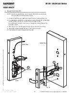
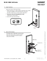
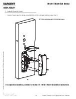
IN120 / IN220 Exit Device
30
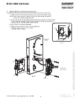
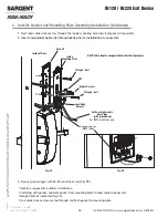
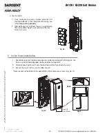
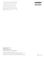
1. Assemble cover by hooking top edge on inside mounting plate taking care not
to pinch gasket (top edge goes between plate and gasket).
2. Carefully press bottom of cover toward door without pinching any wires.
3. Secure the cover with a security allen wrench.
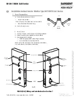
6 Inside Cover Installation
Fig. 5B
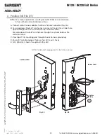
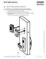
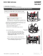
*Note location of installed ferrite bead (IN220 PoE) and excess wires (Fig. 6A, D).
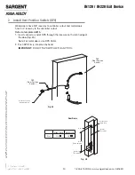
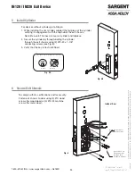
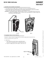
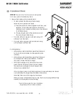
B. IN120 (WIFI)
1. Once controller is securely in place, place (6) “AA”
alkaline batteries in the compartment, being care-
ful to
align polarity properly.
2. After batteries are installed, there is a slight delay;
then an audible “beep” will sound and the lock
motor will cycle.
Security
Allen Screw
Fig. 6A
Fig. 6B
Fig. 6C
Fig. 6D