


PES CY DYNAMIC ROD-LOCKING DEVICE
4
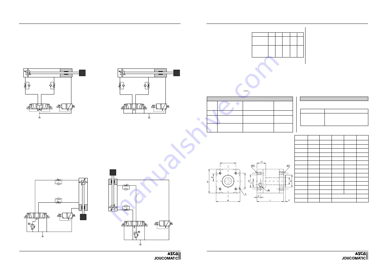
HORIZONTAL MOUNTING
The cylinder is controlled by a 5/3 valve (ISO size 1 for diameters 40 and 50 mm, ISO size 2 for diameters 63, 80 and 100 mm), with
centre open to the central port (type W2 - fi g.1), or centre open to exhaust (type W3 - fi g.2), and supplied by exhaust ports 3 and 5. In
both options, the pressure is maintained on both sides of the cylinder piston and the forces exerted on it are balanced. This prevents
any accidental movement of the rod when it is disengaged. Type W2 is recommended for its simpler wiring. Do not use a 5/3 valve with
closed centre (type W1), since this will unbalance the piston in case one of the components in the circuit leaks.
NOTE
: The cylinder rod may move out slowly after release of the system as a result of the “rod effect”.
One-directional fl ow reducers must be used to control the rate of speed of the rod.
The rod lock device must be activated by a 3/2 NC solenoid valve, with a minimum passage diameter of 8 mm, to ensure fast braking
of the cylinder rod. Locking by absence of air.
VERTICAL MOUNTING
The cylinder is controlled by a 5/3 valve (ISO size 1 for diameters 40 and 50 mm, ISO size 2 for diameters 63, 80 and 100 mm), with
centre open to exhaust (type W3), and supplied by the exhaust ports. To ensure that the lock functions properly, the force on the piston
which is generated by pressure - and which operates in the same direction as the load - must not exceed the locking capacity of the
device when it is combined to the force of the load (see table on opposite page).
Do not use a 5/3 valve with closed centre (type W1) since this will unbalance the piston in case one of the components in the circuit
leaks. This could be hazardous when the rod is disengaged.
Use of a 5/3 (type W3) valve provides a braking effect and ensures that the rod is held in a given position. The stopping precision
depends on the rate of speed of the rod and the loads in motion.
One-directional fl ow reducers must be used to control the rate of speed of the rod.
The rod lock device must be activated by a 3/2 NC solenoid valve, with a minimum passage diameter of 8 mm, to ensure fast braking
of the cylinder rod. Locking by absence of air.
Fig. 2 - Cylinder control with a 5/3 valve,
centre open to exhaust (type W3).
Fig. 1 - Cylinder control with a 5/3 valve,
centre open on central port (type W2).
2
2
4
12
14
1
3
3
5
1
W
2
2
4
12
14
1
3
3
5
1
W
Lowering
control
Lifting
control
Lifting
control
Lowering
control
Fig. 3 - Load
underneath
the cylinder
Fig. 4 - Load
on top of
the cylinder
2
2
4
12
14
1
3
3
5
1
W
Extend
control
Retract
control
2
2
4
12
14
1
3
3
5
1
W
Retract
control
Extend
control
DYNAMIC ROD-LOCKING DEVICE Ø 16-20-25 mm
(Rod-locking device alone)
5
MECHANICAL CHARACTERISTICS
Ø rod (mm)
Holding
force (N)
Speed : 0.5
(m/s)
0.2
16 20 20 25 25
1000 1600 2500 4000 6300
80 130 200 320 500
90 145 225 360 590
FLUID
: Air or neutral gas,
fi ltered, lubricated or not
LOCKING SIGNAL
Min. pressure : 4 bar
Max. pressure : 8 bar
MAX SUPPLY PRESSURE FOR
ROD LOCKING DEVICE
: 8 bar
PNEUMATIC CHARACTERISTICS
HOLDING FORCE (static) :
RESTRAINING CAPACITY
:
Max. load (kg)
that can be stopped dynamically over a distance of 50 mm in
relation to the rate of speed of the rod (the rod must be in vertical position).
RATE OF SPEED OF THE ROD : max. 0.5 m/s
ROD CHARACTERISTICS : see below
IMPORTANT RECOMMENDATIONS
- The rod must have the following characteristics:
-
The rod-locking device must be centered on Ø S1 or S2
•
Dimensional tolerance: h9
(see dimensions below).
•
Hard-chrome plating or hard coating
•
R
•
600 N/mm
2
and Rt = 5 µm
•
There must not be any sharp edges
DIMENSIONS AND WEIGHTS
Ø rod (mm) 16 (h9) 20 (h9)
20 (h9) 25 (h9)
25 (h9)
(2)
N
1000 1600
2500 4000
6300
M
70 75
95 95
120
TG
38 46,5
56,5 72
89
G
4 4
4 4
4
F1
24 30
30 36
40
L
95
112 120
140 150
R
7 -
8 -
-
B
18 -
25 -
-
C
-
12
- -
-
ØE
G1/8 G1/4 G1/4 G1/4 G1/4
K
15,5
22,9
15
21 21
ØD1 M6x13
M8x13 M8x14
M10x28 M10x28
ØD2 M6x13
M8x13 M8x13
M10x34 M10x37
ØS1 Ø35
Ø40
Ø45
Ø55
ØS2 Ø35
Ø40
Ø45
Ø55
(2) : Static holding force (N)
-0.05
-0.1
-0.05
-0.1
-0.05
-0.1
-0.05
-0.1
+0.1
+0.05
+0.1
+0.05
+0.1
+0.05
+0.1
+0.05
TG
TG
Ø MM
Weight of rod-locking device alone (light alloy body)
Model
1000 N : 1.3 kg
1600 N : 1.5 kg
2500 N : 3.1 kg
4000 N : 3.5 kg
6300 N : 5.6 kg
20
1000
88145265
Ø 40
1600
88145266
Ø
50
2500
88145267
Ø 63
4000
88145268
Ø
80
6300
88145269
Ø
100
25
16
Ø rod (mm)
CODES
16
(h9)
88145276
(1)
20 (h9)
88145277
(1)
25 (h9)
88145278
(1)
(1) Length (m) to specify on order (max. length: 3 m).
The rod can be delivered as follows:
ROD
ROD-LOCKING DEVICE
Ø rod
(mm)
Static holding
force (N)
CODE
ROD-LOCKING
DEVICE alone
Mountable
on PES
cylinder/tie rods
ORDERING INFORMATION
PUTTING INTO SERVICE - MAINTENANCE
- Before installing the rod-locking device, it must be pressurised (min. 4 bar, max. 8 bar) to release it. Introduce the rod into the
locking device, taking the following precautions:
•
There must not be any sharp edges on the rod
•
The rod must be perfectly aligned with the centreline of the locking device
•
There must be no point of resistance
- Before fastening the rod-locking device on its mounting support, depressurise the locking device so that it can be centered
correctly on the rod.
- The rod locking device is fi tted with 2 wiper seals made of PUR. It is recommended to grease the rod lightly at regular intervals
with a non-detergent class ISO VG 32 oil without aggressive additives (commonly used in pneumatic circuits). Do not let the
rod come into contact with any other oils or products which might damage the wiper seals made of PUR.
-
It is recommended to check the correct operation of the rod-locking device at regular intervals.


