background image

AP224S GPON HGU User Manual


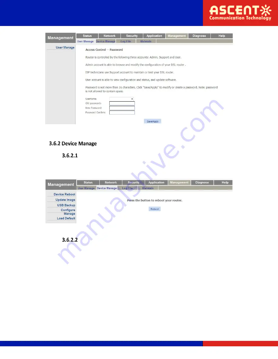
Figure 3-49: User manage 


Device Reboot 

This page allows you to reboot the device. The process of rebooting will take several minutes. 


Figure 3-50: Device reboot 


Update Image 

This page allows you to update the software of the device. You can click the “browse” button 
to select the software you want to update and then click the “Update Software” button to 
update the image. 

Solutions Provider for FTTx, RFoG and HFC    www.ascentcomtec.com 

Page 44 of 79 


Summary of Contents for AP224S

Page 1: ...ACT AP224S GPON HGU User Manual Revision A...

Page 2: ...strictly forbidden This document is produced to assist professional and properly trained personnel with installation and maintenance issues for the product The capabilities system requirements and or...

Page 3: ...8 2 3 Set up Connection 9 Chapter 3 Configuration 10 3 1 Login 10 3 2 Status 10 3 3 Network 14 3 4 Security 29 3 5 Application 33 3 6 Management 43 3 7 Diagnose 47 3 8 Help 49 Chapter 4 Examples 50 4...

Page 4: ...th frame segmentation allowing higher quality of service QoS for delay sensitive voice and video communications traffic AP200C series GPON ONT provides the reliability and performance expected for bus...

Page 5: ...tor SC single mode single fiber Upstream 1 25 Gbps Downstream 2 5 Gbps Wavelength Tx 1310 nm Rx 1490 nm CATV 1550 nm Optical Interface SC APC connector Interface 4 10 100 or 10 100 1000 Mbps auto adap...

Page 6: ...FXS1 port LAN 1 2 3 4 Connect the LAN ports to your devices using RJ45 Ethernet cables WPS Press down Wi Fi turn on off for 3 seconds to enable disable WiFi WiFi Hold down the reset button for 1 to 5...

Page 7: ...ected LED automatically turns off after 5 minutes of successful connection ON WPS client is connected LED automatically turns off after 5 minutes of successful connection Flash WPS client is connectin...

Page 8: ...the optical connector and the optical fiber clean Make sure there are no tight bends in the fiber and that the bending diameter is greater than 6 cm Otherwise the optical signal loss may be increased...

Page 9: ...e ONU chassis refer to Figure 1 5 and two flat head wood screws a Insert the screws into the wall The screw positions must be on the same horizontal line and the distance between them must be 165 mm R...

Page 10: ...Quick Installation to install 2 The device default IP is 192 168 1 1 3 Open your web browser type the device IP into the address bar 4 Entry of the username and password will be prompted Enter the def...

Page 11: ...u have configured The WAN connection s protocol can be configured to IPv4 IPv6 or both of them Figure 3 3 WAN Info xPON Info This page shows the PON information such as temperature voltage current pow...

Page 12: ...me whether security is enabled and packet traffic statistics Figure 3 5 WLAN Interface LAN Interface This page shows LAN information such as LAN gateway information LAN interface packet traffic statis...

Page 13: ...face This page shows VoIP information which includes registration status user status and phone number Figure 3 7 VoIP Info This page shows the request status of ITMS connections Solutions Provider for...

Page 14: ...d a WAN connection if you have eight connections configured because the maximum number of WAN connections is eight Figure 3 9 Internet Parameters Description Uplink Mode The uplink mode is set to GPON...

Page 15: ...ble Open NAT function Disable Close NAT function Enable VLAN Disable In this WAN connection the packets transmitted by the PON port aren t given a VLAN tag Enable In this WAN connection the packets tr...

Page 16: ...LAN rule DHCP HGU servers will not affect the LAN port which is bound to OTHER mode WAN for upstream You can t visit webpages from this port This page allows you to configure LAN interface VLAN Basic...

Page 17: ...VLAN ID is 99 The port is in translation mode The port receives messages with VLAN 77 then translates to VLAN 99 and sends to PON port 4 Received VLAN ID is 0 translation VLAN ID is 0 The port is in t...

Page 18: ...anslation mode The port receives messages with VLAN 77 then translates to VLAN 99 and sends to PON port 4 Received VLAN ID is 65535 translation S VLAN ID is 65535 The port is in transparent mode 5 Rec...

Page 19: ...ived VLAN ID is 0 translation VLAN ID is 10 The multicast VLAN of the port is in tag mode VLAN is 10 2 Received VLAN ID is 10 translation VLAN ID is 10 The multicast VLAN of the port is in trunk mode...

Page 20: ...Add button to configure IP addresses you want to reserve If you want to delete a reserved IP configuration select the Del checkbox and then click the Del button IPv6 This page allows you to configure...

Page 21: ...re bind time By default lease time is 50 of preferred life time and re bind time is 80 of preferred life time Valid Life Time Lease period of IPv6 addresses After a valid life time expires the server...

Page 22: ...ou make WLAN Basic This page allows you to configure basic wireless settings Basic settings include wireless switch settings SSID name country max clients and so on for each SSID You can enable each A...

Page 23: ...y or region Max Clients Max clients for this SSID Security This page is used to configure wireless security Figure 3 18 WLAN Security In WPS Setup you can select whether to enable the WPS Wi Fi Protec...

Page 24: ...hen it is enabled 54g Rate 54g rate Multicast Rate Wireless multicast rate Basic Rate Wireless basic rate Fragmentation Threshold Messages will be segmented if their length is higher than the threshol...

Page 25: ...s based on IEEE802 11e wireless multimedia extension standards In a single network using Xpress technology can improve the total rate of AP by 27 Transmit Power Wireless transmit power Value is 20 40...

Page 26: ...cation username for HGU connecting to ITMS server ACS Password Authentication password for HGU connecting to ITMS server WAN interface Choose a WAN interface for TR069 Connection request username Auth...

Page 27: ...edule depending on the queue settings Figure 3 23 QoS Configuration Parameter Description Mode Row QoS template There are several templates to choose from Enable QoS Enable QoS Upstream Bandwidth Set...

Page 28: ...have selected the check box select the time server and time zone you want to set and then click the Save Apply button to save Figure 3 24 Time server This page allows you to configure static routing...

Page 29: ...68 0 0 16 WAN Interface Select the WAN interface you want to add static route Gateway IP Address Please input the gateway IP address Metric Please input the metric value This page allows you to config...

Page 30: ...checkbox and then click the Del button to remove URL items from the list Security Level This page allows you to configure the firewall level The firewall has three levels Low Medium and High Figure 3...

Page 31: ...Enable MACFilter Filter Mode Black List MAC Addresses in the list are forbidden all others can be accessed White List MAC Addresses in the list can be accessed all others are forbidden MAC Address Inp...

Page 32: ...Filter Direction Ingress Packet ingress for the port will be filtered by the rule Egress Packet egress for the port will be filtered by the rule BOTH Packets of both directions will be filtered by the...

Page 33: ...onfigure in the rule Notice When port filter mode changes to white list you should configure two rules One rule for ingress direction and one rule for egress direction Eg Port_1 filter mode has change...

Page 34: ...rtual Server This page allows you to configure a virtual server You should create a WAN connection with NAT function enabled before you configure the virtual server After you click the Add button you...

Page 35: ...items from the service table Figure 3 35 Virtual Server Parameter Description Use Interface Select a WAN connection with NAT function enabled Service Name Select a service you want to add to the virt...

Page 36: ...nnection that includes VoIP service Region Select the region Proxy Server Enter the IP address or domain name of the SIP proxy server External Proxy Server Enter external proxy server address If the m...

Page 37: ...t should appear on caller ID Username Enter the registration ID of the user with the registrar Password Enter the password used for authentication with the registrar ptime Settings Select the packing...

Page 38: ...ll is active It can be set as 3 modes In Band RFC2833 and INFO message If the mode is set as In band transport the signal from pressing buttons will be transferred along with the voice signal If the m...

Page 39: ...to 120 s Ring Max Duration Set the ringing duration default value is 60 range 30 s to 120 s Call Wait Duration Set the call wait duration default value is 12 range 12 s to 30 s Codec Priority Setting...

Page 40: ...the two lines IGMP SNOOPING This page allows you to enable or disable the IGMP Snooping function Figure 3 41 IGMP Snooping Setting IGMP PROXY This page allows you to enable IGMP proxies for a specifie...

Page 41: ...aging time as well as the MAC address limited Figure 3 44 MAC Limited Setting MLD SNOOPING This page allows you to enable or disable the MLD snooping function for IPv6 just like the IGMP snooping fun...

Page 42: ...XY This page allows you to enable MLD proxies for IPv6 just like the enable IGMP proxy fuction for IPv4 Figure 3 46 MLD PROXY Setting Family Storage This page allows you to build a FTP server Solution...

Page 43: ...sername or password There are two levels for accounts admin and user The admin account is able to access and modify all settings of the HGU The user account can only be used to view configurations sta...

Page 44: ...ill take several minutes Figure 3 50 Device reboot Update Image This page allows you to update the software of the device You can click the browse button to select the software you want to update and...

Page 45: ...you to back up a configuration file to USB storage Figure 3 52 USB backup Configure Manage This page allows you to back up and restore the configuration settings of a router Figure 3 53 Configure man...

Page 46: ...play level etc Figure 3 55 Log settings Parameters Description Log Level Log record level Includes Emergency Alert Critical Error Warning Notice Informational and Debugging Display Level Log display l...

Page 47: ...ows about the maintenance Click the End of maintenance button the new data will automatically be reported to the server Figure 3 57 Maintain This page shows information about the line diagnosis You ca...

Page 48: ...devices Figure 3 59 PING diagnose Parameters Description Interface Select the interface you want to test Destination IP or Host Name Input the destination IP you want to ping Use IP type IPv4 Use IPv...

Page 49: ...oute is in running status This page shows information about the manual send inform test Figure 3 61 Inform reported The Help tab displays information for HGU display instructions and prompts in each w...

Page 50: ...been successfully registered and authorized Connect PC to one of the HGU s LAN ports with a twisted cable Bridge Mode for Internet Service 3 Add a WAN connection Choose Network Internet Internet in t...

Page 51: ...ress from a DHCP server in the network the PC can access the Internet Route Mode for Internet Service 1 Add a WAN connection Choose Network Internet Internet in the navigation menu Add a route mode WA...

Page 52: ...mode of port 1 Figure 4 4 LAN VLAN settings 3 Access the Internet Connect PC to LAN port 1 The PC receives an IP address from the HGU and the HGU receives an IP address from a DHCP server in the netwo...

Page 53: ...V service VLAN is 30 Before configuring make sure the HGU has been successfully registered and authorized Connect PC to one of the HGU s LAN ports with a twisted cable Bridge mode for IGMP 1 Add a WAN...

Page 54: ...tion 2 Configure LAN port Choose Network Internet LAN VLAN in the navigation menu Enable VLAN mode of port 2 Received VLAN ID is 0 and translation VLAN ID is 0 Figure 4 6 Enable LAN VLAN Solutions Pro...

Page 55: ...the box for IGMP snooping IGMP snooping is checked by default It will not be mentioned in previous examples Figure 4 8 Enable IGMP snooping 4 Join multicast group User sends an IGMP report message thr...

Page 56: ...VLAN ID is 30 Service mode is INTERNET Bind port 3 Keep other parameters default Figure 4 9 Add a route WAN connection 6 Enable IGMP proxy Choose Application IGMP IGMP PROXY in the navigation menu Ch...

Page 57: ...HGU works in route mode for IGMP so you should disable the VLAN mode of LAN 3 Figure 4 11 LAN VLAN settings Figure 4 12 Multicast LAN VLAN settings 8 Join multicast group User sends an IGMP report mes...

Page 58: ...fore configuring make sure the HGU has been successfully registered and authorized Connect PC to one of the HGU s LAN ports with a twisted cable 1 Add a WAN connection Choose Network Internet Internet...

Page 59: ...connection for the VoIP you have added Choose which region the VoIP service is used for Different regions have different dial tones ring tones etc Proxy server and registering server are both 192 168...

Page 60: ...s example introduces how to achieve internet service and IPTV service at the same time 1 HGU uses route mode for internet service and bridge mode for IPTV service LAN 1 is used for internet service VL...

Page 61: ...of the HGU s LAN ports with a twisted cable Route and Bridge Mode for Mixed Service 1 Add WAN connections Choose Network Internet internet in the navigation menu Add a route mode WAN connection using...

Page 62: ...gure 4 17 Add a bridge mode WAN 2 Configure LAN VLAN Choose Network Internet LAN VLAN in the navigation menu Disable VLAN mode of LAN 1 Figure 4 18 Set VLAN for LAN1 Set VLAN as 1000 for VOD service i...

Page 63: ...ticast VLAN Choose Network Internet Multicast LAN VLAN in the navigation menu Set multicast VLAN as 1100 for LAN2 Received VLAN is 0 and translation VLAN is 1100 Figure 4 20 Set multicast VLAN for LAN...

Page 64: ...r ISP via DHCP you can watch IPTV Route Mode for Mixed Service 1 Add WAN connection Choose Network Internet internet in the navigation menu Add a route mode WAN connection using the following paramete...

Page 65: ...proxy 3 Configure public multicast VLAN Choose Application Other IPTV in the navigation menu Choose the relevant WAN connection and set public multicast VLAN as 22 Figure 4 23 Configure public multica...

Page 66: ...icast LAN VLAN in the navigation menu Disable multicast VLAN of LAN 2 Figure 4 26 Configure multicast VLAN of LAN 2 6 Access the internet Connect PC to LAN port 1 The PC receives an IP address from th...

Page 67: ...P account 1 88880001 88880001 Account 2 88880002 88880002 Before configuring make sure the HGU has been successfully registered and authorized Connect PC to one of the HGU s LAN ports with a twisted c...

Page 68: ...27 Add a WAN connection for Internet service Add a bridge mode WAN connection for IPTV service Enable VLAN with transparent mode Service mode is other Bind LAN 2 Solutions Provider for FTTx RFoG and H...

Page 69: ...on for IPTV service Add a route mode WAN connection for VoIP service Choose IPv4 and static Input the IP address mask gateway DNS etc Enable VLAN VLAN ID is 100 Service mode is VoIP Solutions Provider...

Page 70: ...ce 2 Configure LAN VLAN Choose Network Internet LAN VLAN in the navigation menu Disable VLAN mode of LAN 1 Figure 4 30 Configure VLAN of LAN 1 Configure VLAN of LAN 2 VLAN ID is 1100 for VOD service S...

Page 71: ...icast VLAN Choose Network Internet Multicast LAN VLAN in the navigation menu Enable VLAN of LAN 2 Input received VLAN ID with 0 and translation VLAN ID with 1100 Figure 4 32 Configure multicast VLAN o...

Page 72: ...hone number username and password of each line Choose packing time default is 20ms Figure 4 33 VoIP general settings 5 Access the internet Connect PC to LAN port 1 The PC receives an IP address from t...

Page 73: ...and encryption method is TKIP AES Before configuring make sure HGU has been successfully registered and authorized Connect PC to one of the HGU s LAN ports with a twisted cable 1 Add a WAN connection...

Page 74: ...figure WLAN basic parameters Choose Network WLAN WLAN Basic in the navigation menu Enable wireless and modify SSID1 s name to xyz For other parameters just configure the suitable ones if necessary Sol...

Page 75: ...ation Choose Network WLAN Security in the navigation menu Select the SSID and set up WPA PSK for its network authentication method and TKIP AES for its encryption method Enter a password in the passph...

Page 76: ...security settings 4 Configure WPS Choose Network WLAN Security in the navigation menu Enable WPS and select Push Button for both client and AP Figure 4 38 WPS settings Solutions Provider for FTTx RFo...

Page 77: ...s the WPS button on the client simultaneously They will connect after a short time You can update software image on webpage Choose Management Device Manage Update Image in the navigation menu Select t...

Page 78: ...nts aren t registered Q PC can t visit web UI A 1 PC and HGU are not in the same network fragment By default LAN IP is 192 168 1 1 24 The default Admin password is vsONU101 2 The cable broke down 3 IP...

Page 79: ...WY 82001 USA Phone 86 21 60232616 Phone 1 203 816 5188 EUROPE VIETNAM Pfarrer Bensheimer Strasse 7a 15 F TTC Building Duy Tan Street Cau Giay Dist 55129 Mainz GERMANY Hanoi VIETNAM Phone 49 0 6136 92...

Reviews: