Ascent Communication Technology EC2200 User Manual Download Page 63


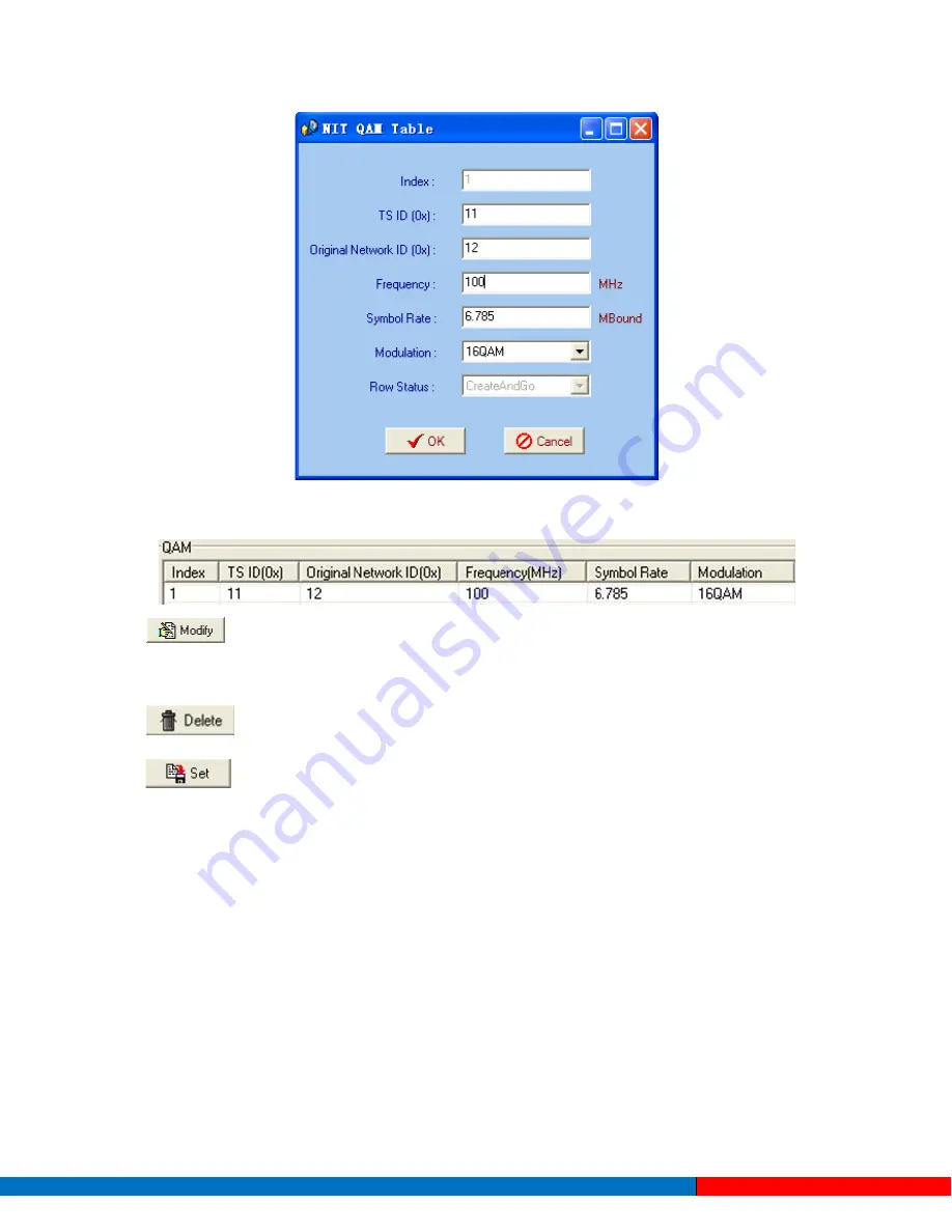
The interface will show as below after the NIT parameters being added


The “Modify” button will trigger a modify window and allow user to modify the 

selected items in the NIT. 

The “Delete” button will remove the selected items in the NIT. 

The set “Button” will send the NIT to the chosen output Port. 

6.1.3


Real-time Monitor 

There will be a real-time bit rate chart generating in the monitor for users to check the bit rate 
information. 


Solutions Provider for FTTx, RFoG and HFC                           www.ascentcomtec.com


Page  63  of  89 


Summary of Contents for EC2200

Page 1: ...ACT EC2200 Encoder Modulator User Guide Revision A...

Page 2: ...nication Technology is strictly forbidden This document is produced to assist professional and properly trained personnel with installation and maintenance issues for the product The capabilities syst...

Page 3: ...re Connection 13 2 4 EC2200 SD Installation 14 2 4 1 EC2200 SD Signal Cable Connection 14 2 4 2 Unbalanced Audio and CVBS Video Input Connection 14 2 4 3 ASI output interface connection 15 2 4 4 IP Ou...

Page 4: ...peration 44 5 2 1 Login Interface 44 5 2 2 Main Interface 45 5 2 3 Adding Frequency Point 46 5 2 4 Adding Equipment under Given Frequency Point 47 5 2 5 Edit Equipment Interface 48 5 2 6 Delete Equipm...

Page 5: ...Ordering Information 88 Chapter 1 Product Introduction 1 1 Outline The EC2200 series HD and SD encoders are multiplexing devices able to provide high quality MPTS outputs for a variety of digital dis...

Page 6: ...le Level 4 0 HD MPEG 2 MP ML SD Supports MPEG 1 Audio Layer II LC AAC and HE AAC V2 HE AAC Supports 720P 1080i 1080P HD video format HD D1 HD1 2 3D1 3 4D1 resolutions SD 0 8 Mbps 19 Mbps each channel...

Page 7: ...I LC AAC HE AAC Sampling Rate 48 kHz 32 kHz 44 1 kHz 48 kHz Bit Rate 64 kb s 384 kb s each channel 32 kb s 384 kb s each channel Multiplexing 1 ASI input multiplexed and 4 SPTS encoding channels 1 ASI...

Page 8: ...1 1 Principle Chart EC2200 8 in 1 MPEG 2 SD Encoder EC2200 4 in 1 MPEG 4 AVC H 264 HD Encoder Solutions Provider for FTTx RFoG and HFC www ascentcomtec com Page 8 of 89...

Page 9: ...been multiplexed 3 UP DOWN LEFT RIGHT keys 4 ENTER key 5 MENU key 6 LOCK key Rear Panel Illustration 1 8 CVBS input ports 7 Data port for IP signal output 2 CVBS input serial numbers from 1 to 8 8 NM...

Page 10: ...CH4 Alarm device stops encoding or encoding error 3 UP DOWN LEFT RIGHT Keys 4 ENTER key 5 Menu Key 6 Lock Key Rear Panel Illustration EC2200 HD HDMI 1 2 3 4 5 6 7 Rear Panel Illustration EC2200 HD SDI...

Page 11: ...er s Manual 1pcs HDMI Cable for EC2200 HD HDMI 4pcs SDI Cable for EC2200 HD SDI 4pcs ASI Cable 1pcs Power Cord 1pcs If any item is missing or different from the list above please contact your local de...

Page 12: ...kg m2 Environment Temperature 5 40 C sustainable 0 45 C temporary Air conditioning is recommended Relative Temperature 20 80 sustainable 10 90 short time Pressure 86 105Kpa Door Window Install rubber...

Page 13: ...device s grounding rod to the frame s grounding pole with copper wire 2 3 Wire Connection The grounding wire conductive screw is located at the right end of the rear panel and the power switch fuse a...

Page 14: ...cable Figure 3 Network cable CAT5 2 4 2 Unbalanced Audio and CVBS Video Input Connection Refer to the connector mark described on the rear panel illustration in section 1 6 to find the CVBS input conn...

Page 15: ...ltiplexer or modulator s ASI input port The encoder s ASI output interface and its connection are illustrated as follow 2 4 4 IP Output Interface connection Users can firstly find the DATA interface o...

Page 16: ...s NMS connecter while the other end to the computer or the PC The encoder s NMS connection is illustrated as follows 2 5 EC2200 HD Installation 2 5 1 EC2200 HD Signal Cable Connection The signal conn...

Page 17: ...ording to the connector mark described on the rear panel illustration and then connect the HDMI or SDI cable in the accessories One end is connected to the head end equipment and the other end to the...

Page 18: ...Users can first find the DATA interface on the device according to the connector mark described on the rear panel illustration and then connect the network CAT5 One end of the network cable is connec...

Page 19: ...tions or confirms changes after modification MENU Cancels presently entered value or restores previous settings and returns to the previous menu LEFT RIGHT Moves the to choose or set the parameters UP...

Page 20: ...tting 3 Output Setting 4 Network Setting 5 Saving Config 6 Loading Config 7 Version SNMP 8 Language The option with is the current selection users can press the ENTER key to enter the specified submen...

Page 21: ...1 1 1 6 Aspect Rati 1 1 1 7 Coding Type 1 1 1 8 Resolution 1 1 1 9 Rate Mode 1 1 1 A Bit Rate 1 1 1 B Max Bit Rate 1 1 1 C Gop Struct 1 1 1 D Video Sharp 1 1 1 E MP4 Profile Input This is for users to...

Page 22: ...rs of the input video in submenus of Brightness Contrast Saturation and Hue The adjustable range is 0 255 while the adjustable range of Hue is 128 127 The figure outside the parentheses is a decimal w...

Page 23: ...resolution Refer to section 1 3 for details Pressing 1 1 1 8 the operation interface will display the following page Rate Mode User can choose CBR VBR at this menu CBR Constant Bit Rate means that the...

Page 24: ...s closed Users can refer to the following interface for details 1 1 1 D Video Sharp 01 01 Close Flat Common Sharp MP4 Profile Setting Users can set the MP4 Profile in this interface and the LCD will d...

Page 25: ...t the relevant audio sample rate by moving the UP DOWN keys After setting the sample rate users can press the ENTER key again to take the modification into effect and the LCD will display the followin...

Page 26: ...below Video Audio PMT PCR PID Settings Users can set these parameters by pressing ENTER to enter these submenus The LCD will display the following pages The maximum PID number cannot exceed 0x1fff 1...

Page 27: ...l Packet Users can choose YES filter the null packet or NO don t filter null packet 3 2 1 4 Program Mux Setting Users can decide whether to open the multiplexing function of the device Channel Mux 1 1...

Page 28: ...splay the following page Prog 006 means the input program is 6 and Out 003 means 3 of the 6 programs have been multiplexed 2 1 Parse ASI Prog 3 2 3 Output Setting By pressing the ENTER key in the main...

Page 29: ...nterface will display the following page 3 2 IP Out Address 224 002 002 002 3 2 3 3 IP Out Port In this menu users can set the encoder IP output port number by press the ENTER key to enter the main ed...

Page 30: ...t the time as needed and it will then generate the TDT table and show in the user s STB 3 2 3 9 Null Packet 3 2 4 Network Setting Users can set the network parameters by pressing the ENTER key and the...

Page 31: ...are otherwise the IP output data will be filtered out when the IP stream passes through the router 3 2 5 Saving Configuration Users can save modifications by pressing the ENTER key and the following i...

Page 32: ...hardware version and the LCD will display the following interface when users press the ENTER key 3 2 8 Language Users can select the interface language under this submenu 8 in 1 Encoder SW 2 05F HW 02...

Page 33: ...en parameter is inactivated LOCK ToLock the screen cancel the lock state After pressing lock key the system will question the users to save present setting or not If not the LCD will display the curre...

Page 34: ...video input parameters and select programs to multiplex The LCD will display 4 submenus which from Encoding Channel 1 to Encoding Channel 4 The setting principle is the same for Encoding Channel 1 4 s...

Page 35: ...video scene changing Profile Users can select the configuration of H 264 profile at this menu The H 264 High Profile code format and Main Profile code format are the available options Level User can s...

Page 36: ...pages 1 1 2 1 Bit rate 01 03 64 Kbps 96Kbps 112Kbps 128Kbps 1 1 2 1 Bit rate 02 03 160 Kbps 192Kbps 224Kbps 256Kbps 1 1 2 1 Bit rate 03 03 320 Kbps 384Kbps Audio Format Setting AAC Advanced Audio Codi...

Page 37: ...deo Audio PMT PCR PID Settings Users can set these parameters by pressing ENTER to enter these submenus The LCD will display the following pages and the maximum PID number cannot exceed 0x1fff 1 1 3 2...

Page 38: ...packet or NO don t filter null packet to decide whether to filter the null packet or not 4 2 1 4 Program Mux Setting Users can decide whether to open the multiplexing function of the device Channel Mu...

Page 39: ...e following page Prog 006 means the input program is 6 and Out 003 means 3 of the 6 programs have been multiplexed 2 1 Parse ASI Prog 4 2 3 Output Setting By pressing the ENTER key in the main editing...

Page 40: ...y the following page 3 2 IP Out Address 224 002 002 002 4 2 3 3 IP Out Port In this menu users can set the encoder IP output port number by press the ENTER key to enter the main editing interface 3 3...

Page 41: ...TS Package Num User can set the amount of TS packages by entering into below interface 4 2 4 Network Setting Users can set the network parameters by pressing the ENTER key and the LCD will display th...

Page 42: ...re otherwise the IP output data will be filter out when the IP stream passes through the router 4 2 5 Saving Configuration Users can save the modification by pressing the ENTER key and the following i...

Page 43: ...dware version and the LCD will display the following interface when users press the ENTER key 4 2 8 3 2 8 Language Users can select the interface language under this submenu 4 in 1 Encoder SW 0 02F HW...

Page 44: ...exe is 4 12 English version or place different versions of network management software to the same directory When the network management software is running it will generate two documents as follows N...

Page 45: ...n interface will appear 5 2 2 Main Interface Users can create a device node tree in the left column by adding modifying and deleting the device node This software provides a powerful node operation fu...

Page 46: ...confirm the given frequency when the user clicks OK User can also right click to pop up the short cut menu in the device tree or in the left blank column and the corresponding dialog box will pop up...

Page 47: ...should choose the frequency point in advance and then the dialog box of Add Equipment will pop up when user clicks the Add Equipment item in the Edit pull down menu on the menu row Solutions Provider...

Page 48: ...is 192 168 2 136 You can check its IP address in the front panel of device in case the IP has unexpectedly changed 2 The PC IP address and device IP address should be in the same network For example...

Page 49: ...n choose the equipment to be deleted in the left column and then click the delete item in the pull down menu which appears by clicking the right mouse key Solutions Provider for FTTx RFoG and HFC www...

Page 50: ...ed values by clicking Alternatively user can also click the button on the toolbar to popup the save file dialog box which gives prompts to save all the device s parameters as binary files in the compu...

Page 51: ...interface is mainly composed of encoding video parameters audio parameters and the encoding system parameters output parameters and etc 5 3 1 Parameters Setting Users can click Equipment Name on the...

Page 52: ...well IP Out Service IP Address Users can set the service IP and the TS output address by modifying the value in these two fields Pay attention to the 2 situations below MPTS Keep the Service IP Addre...

Page 53: ...s device supports 1 MPTS Multiple Programs Transport Stream and 8 SPTS Single Programs Transport Stream output User can click to triger a pull down list to select the output type Device Mode User can...

Page 54: ...ent device s activating parameters Input channel selection area The interface and setting principle of each channel are the same User can set the mode or type of each item by clicking the Radio Box un...

Page 55: ...ach item in this area by clicking the pull down trigger User cans set the Audio Gain value by moving the slider directly inputting the value in the right box The adjustment range is 0 16 Solutions Pro...

Page 56: ...ice IP and the TS output address by modifying the value in these two fields Original Network ID This 16 bit field gives the label identifying the network ID of the originating delivery system The valu...

Page 57: ...eover user can modify the output programs Program Name PMT PCR video audio PID Check this box the set the PID Mapping To refresh the inputting terminal and get the inputting information To refresh the...

Page 58: ...can select the target program in output part first and click this button to pop up a dialog box as below Select the target item and input the new value in the box below then click and to effect the m...

Page 59: ...fect Refresh getting PID filter table from the device Setting submitting the PID filter table to the device Check All selecting all the selections of the list After user selects one PID in the table t...

Page 60: ...ng to any program such as EPG NIT tables and so on but user just wants to pass them through the multiplexing module without changing anything This is the main purpose of this function The display will...

Page 61: ...click OK to confirm The PID then will be bypassed and listed in the table as below User can also modify or delete the added PID through the corresponding buttons at right 6 1 2 3 NIT Parameters NIT Ne...

Page 62: ...descriptor The Descriptor Data is the detailed information of the private description Replace NIT Table After checking the checkbox the NIT editing menu is active And also the device will insert the E...

Page 63: ...ted items in the NIT The Delete button will remove the selected items in the NIT The set Button will send the NIT to the chosen output Port 6 1 3 Real time Monitor There will be a real time bit rate c...

Page 64: ...way the configuration can only be saved temporarily and will restore the last saved configuration if the device reboots To save the configuration permanently it is required to operate through Remote S...

Page 65: ...confirm Users can then note the indicator light turns red which signifies the equipment has disconnected Users then can refer to below prompts to edit the property by inputting the new IP to re connec...

Page 66: ...low dialog box will pop out as shown below Select the Edit Information by marking the check box with user can input the new username and new password as prompts below It is required to click to add th...

Page 67: ...s running and give user prompts to input user name and password The default user name is admin and no password User can add users and passwords as needed Details please refer to section 4 4 3 The menu...

Page 68: ...by adding modifying and deleting the device node This software provides a powerful node operation function and the user can edit various parameters in the device tree for management and classification...

Page 69: ...firm the given frequency while user clicks OK User can also click right mouse key to pop up the shortcut menu in the device tree or in the left blank column then the corresponding dialog box will pop...

Page 70: ...g box of Add Equipment will pop up when user clicks Add Equipment item in the Edit pull down menu on the menu row 7 2 5 Edit Equipment Interface Chapter 8 User should follow the steps as below Inputti...

Page 71: ...he front panel of device in case the IP changed unexpected 2 The PC IP address and device IP address should be in the same network For example the Device IP is 192 168 002 136 sub mask is 255 255 255...

Page 72: ...toolbar to save the modifications to the device s flash while user can also reload the saved parameters from device s flash and refresh the device s parameters setting according to the loaded values...

Page 73: ...the device tree the procedure will display the encoder interface in operating area The interface is mainly composed of encoding video parameters audio parameters and the encoding system parameters ou...

Page 74: ...he IP output is enabled otherwise it is not Users can decide whether to open the IP output function or not Users can modify the IP address here as well IP Out Address Service IP Address Service Mask S...

Page 75: ...0 to 0xFFFF Output Bit Rate Mbps This includes the effective bit rate of encoding channel 1 8 the effective bit rate from ASI input and the bit rate of stuffed null packets UDP Stream TS Package User...

Page 76: ...e s activating parameters Input channel selection area The interface and setting principle of each channel are the same Video Config Area It is to configure video manually exceptresolution which autom...

Page 77: ...inputting information To refresh the outputting terminal and get the outputting information Multiplex the input programs to the output channels after selecting the target program with The system will...

Page 78: ...fect the modification The parsing overtime value 8 2 3 Tables 8 2 3 1 PID Filter Table Users can operate PID filter in this table by checking the check boxes of corresponding items and click CONFIRM t...

Page 79: ...stream 8 2 3 2 PID Pass User can decide to bypass the inputting PID as needed in this interface In some occasions there are some PIDs which won t belong to any program such as EPG NIT tables and so on...

Page 80: ...s needed and click OK to confirm The PID then will be bypassed and listed in the table as below User can also modify or delete the added PID through the corresponding buttons at right 8 2 3 3 NIT Para...

Page 81: ...ert the private descriptor into the output TS The private descriptor includes two parts One is descriptor tag and the other is descriptor information The Descriptor Tag is an 8 bit field which identif...

Page 82: ...ded The Modify button will trigger a modify window and allow user to modify the selected items in the NIT The Delete button will remove the selected items in the NIT The set Button will send the NIT t...

Page 83: ...t in which way the configuration can only be saved temporarily and will restore the last saved configuration if the device reboots To save the configuration permanently it is required to operate throu...

Page 84: ...e new NMS IP Address for the device and click OK button to confirm Users can then note the indicator light turns red which signifies the equipment has disconnected Users then can refer to below prompt...

Page 85: ...r name is admin and no password User can add users and passwords as needed User clicking Setting in the menu bar and selecting User Setting in the pull down list the below dialog box will pop out as s...

Page 86: ...Solutions Provider for FTTx RFoG and HFC www ascentcomtec com Page 86 of 89...

Page 87: ...on the rear panel and other heat sink bores if necessary Checking the input AC within the power supply working range and the connection is correct before switching on device Checking the RF output lev...

Page 88: ...ns on input output options Model Description EC 22 04 HDMI AC EC2200 HD H 264 Encoder 4 HDMI to ASI IP outputs AC Power EC 22 08 AV AC EC2200 SD MPEG II Encoder 8 AV to ASI IP outputs AC Power Solutio...

Page 89: ...one 86 21 60232616 Phone 1 203 816 5188 EUROPE VIETNAM Pfarrer Bensheimer Strasse 7a 15 F TTC Building Duy Tan Street Cau Giay Dist 55129 Mainz GERMANY Hanoi VIETNAM Phone 49 0 6136 926 3246 Phone 84...

Reviews: