AsahiAV H-A077-E-00 User Manual Download Page 1


Installation, Operation and Maintenance Manual


H-A077-E-00

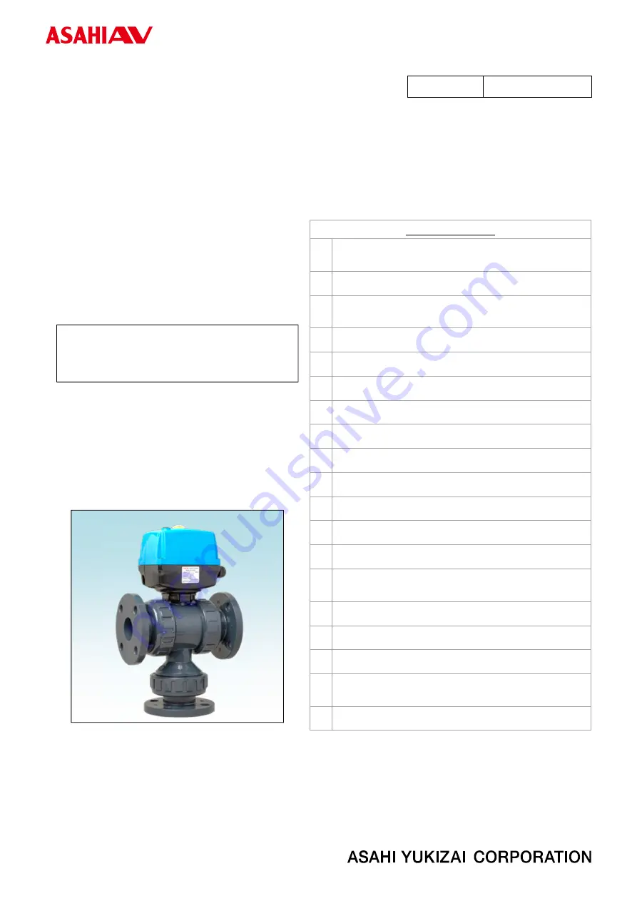
  3-Way Ball valve Type 23    Electric actuated Type Z 15

50mm (½”-2”)   


Serial No.


H-A077-E-00


Table of contents


1.


Be sure to read the following warranty clauses 
of our product 

 ······································· 

  1


2.


General operating instructions 

 ·················· 

  2


3.


General instructions for transportation, 
unpacking and storage 

 ··························· 

  4


4.


Name of parts 

 ······································· 

  5


5.


Maximum working pressure vs. temperature 


  7


6.


Specifications of valves 

 ··························· 

  7


7.


Specifications of actuator 

 ························ 

  8


8.


Installation procedure 

 ··························· 

  10


9.


Support setting procedure 

 ····················· 

  17


10.


Electric wiring procedure 

 ······················· 

  18


11.


Operating procedure 

 ···························· 

  20


12.


Adjustment of limit switches procedure 

····· 

  23


13.


Actuator removal procedure 

 ··················· 

  24


14.


Method of adjusting face pressure between ball 
and seat 

 ············································ 

  25


15.


Disassembling method for replacing parts 

· 

  26


16.


Inspection items 

 ·································· 

  28


17.


Troubleshooting 

 ·································· 

  28


18.


How to inquire about defects or replacement     

 ························································· 

  30


19.


Handling of residual and waste materials 

 ·· 

  30


3-Way Ball valve Type 23 

Electric actuated Type Z 

(15〜50mm [

½

”-2”])


Userʼs Manual 


Summary of Contents for H-A077-E-00

Page 1: ...e 7 6 Specifications of valves 7 7 Specifications of actuator 8 8 Installation procedure 10 9 Support setting procedure 17 10 Electric wiring procedure 18 11 Operating procedure 20 12 Adjustment of li...

Page 2: ...ations or other documented approval The related technical documents operation manuals and other documentation prescribe precautions on selecting constructing installing operating maintaining and servi...

Page 3: ...properly Do not use AV valves in a place where they may become submerged in water Do not apply a great impact or vibration to the actuator The surface temperature of the actuator may rise during opera...

Page 4: ...e contact for the left open right open signal within the contact capacity 1A May be damaged Use a commercially available Allen wrench for manual operation Keep the ambient temperature of the installed...

Page 5: ...etc These chemicals may cause damage to the valve Store products in their corrugated cardboard boxes Avoid exposing products to direct sunlight and store them indoors at room temperature Also avoid st...

Page 6: ...Bolt 2 Ball 9 O ring B 19 Connector plate 3 Carrier 10 O ring C 20 Bolt 4b End connector Flanged end 11 O ring D 21 Rubber cap 4c End connector Socket end 12 O ring E 22 Rubber cap 4d End connector T...

Page 7: ...for signal output Attachment Sealing plug NBR rubber 3 LED lamp 11 Space heater 4 Indicator 12 Terminal block for grounding 5 Bush for manual operation 13 Terminal block for power input 6 Bolt cap 14...

Page 8: ...Body material PVDF JIS socket is not produced The spigot type is DIN standard only and the body material C PVC is not produced NOTE A Automatic 23 Type 23 Z Type Z U 95 240VAC U U PVC E EPDM F Flanged...

Page 9: ...arbonate blue flame retardant UL94V 0 Body Polycarbonate with glass black flame retardant UL94V 0 Function State output 5 Left open Right open output 1 place each Non voltage contacts Contact capacity...

Page 10: ...ct limit switch The valve may not be left fully closed or right fully closed and may leak The wiring diagram shows the end of the left open operation OLS 1 Left open limit switch SLS 1 Right open limi...

Page 11: ...mpact or other excessive stress When installing disassembling or reassembling the piping fix the End connector When installing a piece of equipment at the end of the piping line be sure to keep the se...

Page 12: ...n nut is loosen or remove please install in the following way Procedure 1 Make sure that the O ring A is properly mounted to the body 2 Set the End connector directly on the body without allowing the...

Page 13: ...her excessive stress The Union nut of this product is fastened lightly so that it can be loosened easily Be sure to remove the end connector before carrying out the work Failure to so may cause extern...

Page 14: ...rdly with hand 5 Using a spanner wrench or motor wrench screw in the end connector by turning 180 360 1 2 to 1 turns carefully without damaging it 6 Make sure that the O ring A is properly mounted to...

Page 15: ...talling pipes and valves ensure that they are not subjected to tension compression bending impact or other excessive stress The Union nut of this product is fastened lightly so that it can be loosened...

Page 16: ...dhesive insert the pipe quickly to the End connector and leave it alone for at least 60 seconds 7 Wipe away overflowing adhesive 8 Make sure that the O ring A is properly mounted to the body 9 Set the...

Page 17: ...The valve can be damaged Do not use a pipe wrench when tightening the union nut The valve can be damaged Be sure to conduct a safety check on all hand and power tools to be used before beginning work...

Page 18: ...ype clamp or something similar take care not to over tighten Excessive force may damage the pipe Do not subject the valve to pump vibrations The valve may be damaged Be sure to conduct a safety check...

Page 19: ...contact with each other There is a risk of short circuit and fire Tighten the cable gland securely with the recommended tightening torque 3 N m There is a risk of electric leakage or electric shock du...

Page 20: ...driver Flathead to connect the Rod type solderless terminal or the tip of the lead to the terminal block with the recommended tightening torque of 0 15 to 0 18 N m according to the wiring diagram Refe...

Page 21: ...ipment damage Check that Auto Manual Changeover switch is fully turned to manual mode then perform manual operation In the case of malodor overheating or smoking turn off the power supply immediately...

Page 22: ...open side and right open side and operate within the following range as a guide Type23 10 100 degree 5 When the manual operation is complete remove the hexagon wrench from the manual operation shaft...

Page 23: ...the external changeover switch and check that the valve display direction and operating direction match 3 Left fully open or right fully open and check that the LED lamp on the top of the cover light...

Page 24: ...len wrench and check that the limit switch operates with the adjusted opening If the adjustment is insufficient repeat steps 4 to 7 There are built in mechanical stoppers on the left open side and rig...

Page 25: ...ons of the valve stem and shaft adapter are correct 2 Check the fitting position of the top flange of the valve and the base plate 3 Push the base plate onto the valve until its claws firmly catch the...

Page 26: ...with the concave part of the Carrier 10 Rotate the Carrier to adjust the surface pressure 11 Attach the handle for manual valve to the stem and confirm that manual operation can be performed smoothly...

Page 27: ...8 Remove the O ring A at the Carrier 9 Engage the upper convex part of the handle with the concave part of the Carrier 10 Turn the handle and remove the Carrier 11 Remove the seat O ring B and O ring...

Page 28: ...f Disassembly When attaching a seat confirm the front and rear sides of the seat When installing the actuator on the valve check that the opening display of the actuator matches the direction of the s...

Page 29: ...en the right closed or left closed 17 Troubleshooting Problem Cause Treatment The Allen wrench does not turn or cannot turn during manual operation The built in stopper left open side or right open si...

Page 30: ...supply voltage is different Check the voltage with the tester and connect it to the correct power supply line The length of the power cable is long Set the cable length to 100 meters or less Refer to...

Page 31: ...emedy a defect even if you take measures against the defect or take corrective actions or when a part needs to be replaced check the information on the labels attached to the actuator and valve and co...

Page 32: ...al Information in this manual is subject to change without notice April 2022 H A077 E 00 3 Way Ball valve Type 23 Electric actuated Type Z 15 50mm 2 3 Way Ball valve Type 23 Electric actuated Type Z 1...

Reviews: