background image

downtown

8

DOWNTOWN CONNECTION

Installation guide

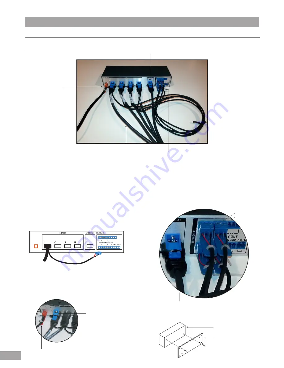
Connections of the electronic box

Step 1 :
Connect the four HDMI data sharing cables. Refer to the instructions 
included with the Downtown Connection system.

IMPORTANT
- The connections (black and red cables) of the HDMI cable #1 must be 
inserted into one of the blue connectors. Than plug the connector into 
the reserved space #1.  

Repeat the same procedure for the HDMI data sharing cables
#2, 3, 4.

Step 2 :
Secure the 4 HDMI data sharing cables with the blue plastic locks 
included. Refer to the Downtown Connection installation guide 
included with the system and refer to the  picture below.

Blue plastic lock

Screw the blue lock in the electronic box 

and fix it with a tie wrap.

Step 3 :
Connect the electrical cable (orange) to the electronic box. 
This cable is linked with the transformer. Once the installation is 
complete, connect the transformer to the power bar.

Electrical cable (orange)

Step 4 :
Connect the HDMI cable for monitor to the electronic box.
Once the installation is complete, connect this cable to the monitor.

Step 5 :
Screw the black metal plate provided by Artopex to the eletronic box.

Under the electronic box

''ARTOPEX'' metal plate

Electrical cable (orange)

4 x HDMI data sharing cables

HDMI cable for monitor (output)

Connectors (black and red wires)

Blue plastic connectors

Black wires : tally output

Red wires : contact

Monitor cable

Summary of Contents for downtown

Page 1: ...Installation guide Update August 2016...

Page 2: ...downtown 2 Installation guide...

Page 3: ...12 Panel with the Downtown Connection system 13 Installation of D C in the mobile panel 13 Downtown Connection Electronic connections 8 Installation of D C on table with architectural base 9 Installa...

Page 4: ...ed on the correct side of the seating Example Part A Left side Part B Right side Step 3 Screw part A under the seating 1 under the frame NOTE Center part A between the legs Seating 1 Seating 2 Step 4...

Page 5: ...ft the vertical cable conduit to remove it Step 1 Screw the metal leg to the surface using the pre drilled holes Legs positioning under the surface Bistro table with multi outlet Step 1 Place all part...

Page 6: ...able and the beams Step 3 If applicable install the multi outlet For access to the interior of technical panel see p 7 Technical panel Surface Structural beam Gable M4 pivoting multi outlet module Ins...

Page 7: ...metal plate located on the top of technical panel Lift the panel and remove it Back lower panel Remove the 2 screws located at the bottom of panel Lift the panel and remove it The construction of tec...

Page 8: ...the system and refer to the picture below Blue plastic lock Screw the blue lock in the electronic box and fix it with a tie wrap Step 3 Connect the electrical cable orange to the electronic box This c...

Page 9: ...Transformer Transformer wire connected to the power bar Step 6 Screw the HDMI cable access module under the surface using the pre drilled holes 6 screws to install Place and screw the surface onto pla...

Page 10: ...panel using the pre drilled holes 4 screws to install Electronic box Step 4 Line up the black metal support with the pre drilled holes on the technical panel Place a cable in each of the slots Attach...

Page 11: ...cable access module and plug into the power bar Use the cable fastener to hold the excess cable Insert the communication punch out plate Black plastic ring Electrical outlet Communication punch out p...

Page 12: ...l outlet cable in the cable conduit and plug it into the power bar Repeat the steps for the monitor cable Cable conduit To remove the cover pull it towards you Step 2 Remove the back panel and install...

Page 13: ...nt of mobile panel Install the monior Back of mobile panel Remove the metal top cap Metal plate Removable laminate panel Installation of Downtown C in the mobile panel The Downtown Connection must be...

Reviews: