OPERATING AND MAINTENANCE MANUAL FU 321M
26
ELECTRIC EQUIPMENT
The electric power supply of the machine is realized through a 3 phase power
supply line with a voltage and frequency being specified in the "Packing list or
on the data plate, placed of the electric box door.
The electrical equipment secures a normal operation of the machine with input
power supply fluctuations of ±10 % and frequency fluctuations of ±2% of the
rated values.
The electrical power supply is realized by power cable 4x6 mm
2
when four-wire
mains is used and 5x6 mm
2
in case of five-wire mains. The cable passes through
the electric inlet, placed on the electric box. It is connected to main breaker's Q1
terminals L1, L2, L3 and, depending on the mains type, to the terminal PE or N,
situated close to the main breaker Q1.
After the connection check whether the movements directions of machine corre-
spond to those set by means of the control levers and change the phase sequence
on two of terminals L1, L2 or L3 when it is necessary.
The degree of protection of the machine is IP44 according EN 60529.
The electric circuit diagram and the wiring diagram are presented on Fig.16 and
Fig.17.
Summary of Contents for FU 321M
Page 32: ...OPERATING AND MAINTENANCE MANUAL FU 321M 29 ELECTRIC EQUIPMENT DETAILS...
Page 33: ...OPERATING AND MAINTENANCE MANUAL FU 321M 30 ELECTRIC ARRANGEMENT...
Page 34: ...OPERATING AND MAINTENANCE MANUAL FU 321M 31 BUTTON ARRANGEMENT FRONT PANEL 10...
Page 35: ...OPERATING AND MAINTENANCE MANUAL FU 321M 32 BUTTON ARRANGEMENT SIDE PANEL WARNING...
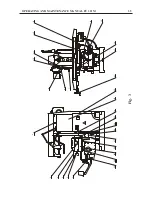
Page 39: ...OPERATING AND MAINTENANCE MANUAL FU 321M 36 Fig 3a 45 41 46 51 48 43 52 44 42 53 49 50 47...
Page 40: ...OPERATING AND MAINTENANCE MANUAL FU 321M 37 SEMI AUTOMATIC CYCLE...
Page 43: ...OPERATING AND MAINTENANCE MANUAL FU 321M 40 Fig 6 1 2...
Page 46: ...OPERATING AND MAINTENANCE MANUAL FU 321M 43 Fig 10 4 3 2 1...
Page 52: ...OPERATING AND MAINTENANCE MANUAL FU 321M 49 Fig 16 3 ELECTRIC CIRCUIT DIAGRAM...
Page 57: ...OPERATING AND MAINTENANCE MANUAL FU 321M 54 Fig 18 3 4 1 2 1 1 1 1 1 1 7 5 6 1 1...
Page 60: ...OPERATING AND MAINTENANCE MANUAL FU 321M 57 Fig 21 OPERATOR S WORKING POSITION ON THE MACHINE...
Page 62: ...OPERATING AND MAINTENANCE MANUAL FU 321M 59 Fig 23 MARKING ON THE PACKING 2170 2370...
Page 63: ...OPERATING AND MAINTENANCE MANUAL FU 321M 60 Fig 24 DIGITAL READOUT SYSTEM...


