


0MNA080A55-GB REV 01 page 47 / 75
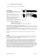
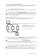
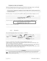
Procedure b)
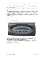
The by-pass line is outside the acceptance field; the following message is seen on the
display panel:
BAD BYPASS VOLTAGE or SWBY OFF and the green LEDs 1 will flash
(see page 50)
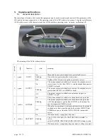
1.
open all the switches on the device (SWIN, SWOUT, SWBY and the battery cabinet
disconnectors/fuses). The control panel will remain off.
2.
before closing switches SWMB and connecting the loads, ensure that both the frequency and voltage
of the supply line are sufficient to power the connected loads.
N.B.: After carrying out the operations indicated above, personnel must wait around ten minutes for the
capacitors to discharge before working on the inside of the SENTRY MPS-HP.
After the maintenance operations have finished, restart the UPS by following the instructions in the section on
START-UP PROCEDURE (see page 43) and then open disconnector SWMB (if closed).
The SENTRY MPS-HP will return to NORMAL OPERATION.
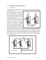
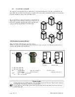
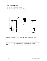
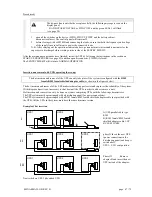
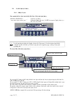
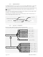
Insertion and removal with UPSs operating (hot swap)
The hot insertion and removal of the UPS can only take place if the system is configured with the
RJ45
female/RJ45 female
shielded adaptor cable
(as shown in the figures below).
The hot insertion and removal of the UPS makes technical support easier and improves the reliability of the system.
With this procedure it is not necessary to shut down all the UPSs in order to add or remove a unit.
Hot insertion and removal can only be done on systems comprising UPSs with the following characteristics:
The UPS system must be prearranged with a distribution panel (for power connections)
The UPS system must be prearranged with a RJ45 female/RJ45 female shielded adaptor cable (not provided with
the UPS)
.
All the UPSs in the system must have the same firmware version.
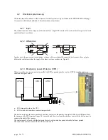
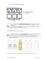
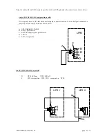
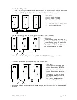
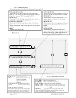
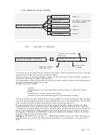
Example of hot insertion
A)UPS parallel cable type
RJ45
B) RJ45 female/RJ45 female
shielded adaptor cable
UPS
BY-PASS CABLE
phase II Insert the new UPS
(power connections in the
distribution panel) and keep it
switched off.
UPS 3: SW1 cont position.
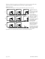
Phase III
Remove
adaptor B and insert the new
UPS instead of the adaptor
.
Now switch on UPS 3 (the added UPS).
UPS 3
A
UPS 1
A
UPS 2
A
I
II
III
B
UPS 1
UPS 2
UPS 3
UPS 1
UPS 2


