


page 20 / 75 0MNA080A55-GB REV 01
3.3
Connection of signals and remote commands
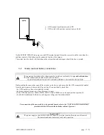
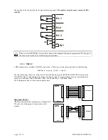
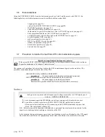
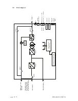
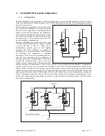
In order to access the interface cards, open the door and remove the protection panel secured with screws (K) as
shown in the drawing:
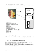
A-
PARALLEL (optional)
B-
EPO (emergency power off control)
C-
REMOTE COMMANDS AND ALARMS
D-
RS232-2
E-
RS232-1
F-
SLOT 1 (main)
G-
SLOT 2 (aux)
H-
REMOTE ALARMS (optional)
I-
REMOTE ALARMS (optional)
L- MODEM (optional) or MULTI I/O (optional)
M- BATTERY TEMPERATURE SENSOR (optional)
N- UGS (optional)
P- SWOUT aux
Q- SWMB aux
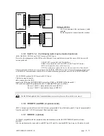
3.3.1 Parallel (optional)
-A-
To be used for the connection of UPSs in parallel configuration. See the chapter “parallel version” on page 35.
3.3.2 EPO connector (emergency power off control)
-B-
If the jumper on the connector is opened, the voltage on the UPS output will be cut.
The UPS is factory-fitted with the EPO terminals shortcircuited. If this input is used, the UPS can be shut down in a
hazardous situation from a remote position simply by pressing a button.
If only the power supply is removed, for example by opening the switch of the power supply panel, the UPS will
keep the load powered using the energy in the batteries.
F
G
E
D
B
C
N
A
L
I
K
H
P
M
Q


