


0MNA080A55-GB REV 01 page 35 / 75
4.
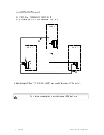
Sentry MPS-HP in parallel configuration
4.1 Introduction
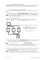
SENTRY MPS-HPs may be connected in a parallel configuration to increase both the reliability of the power supply
to the load and the power available in output. Up to 8 UPSs can be parallel-connected. It is recommended to connect
units of the same power.
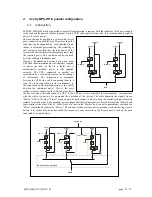
The load that can be applied to a system with several
units connected in parallel may be greater than the
load that can be supported by each individual unit,
thanks to automatic power sharing. The reliability is
only increased provided that the total power of the
system with one unit deactivated remains greater than
the required power. This condition can be achieved
by always adding a redundant unit.
Having a redundant unit means having one more
UPS than the minimum number of elements required
to power the load, so that if a faulty unit is
automatically excluded, power is still supplied
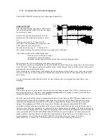
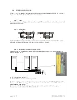
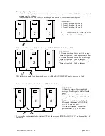
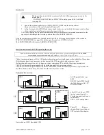
correctly. The UPSs connected in parallel are
coordinated by a card which ensures the interchange
of information. The information is exchanged
between the UPSs via a cable connecting them in a
loop. The loop connection provides redundancy in
the connection cable (communication in the cables
between the individual units). This is the most
reliable means of connecting the UPS and also allows
the hot insertion or disconnection of a UPS. Each UPS has its own controller that continuously communicates
with the whole system so as to guarantee the operation of the system. The cable transmits the signals from a
“Master” UPS to the other “Slaves” using an opto-isolated system in order to keep the control systems electrically
isolated from each other. The operating logic envisages that the first unit that is activated becomes the “Master” and
takes control of the other “Slaves”. In the event of a fault in the “Master” unit, control is immediately switched to a
“Slave” which then becomes the “Master”. The current system provides basic operation, each unit having its own
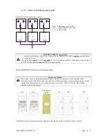
battery. The system may be personalized (by means of a code inserted on the display panel) with all the units
connected to a single battery.
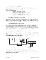
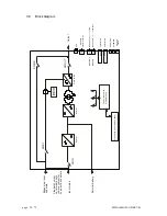
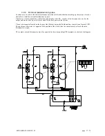
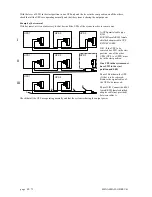
Battery
by-pass
line
load
mains
mains
Battery
by-pass
line
by-pass line
By-pass cabinet (optional)
Load
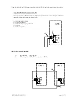
UPS 1
UPS 2
UPS 3 ---UPS 8
mains
line
Battery
mains
line
mains
line
Battery
Battery


