IPN-8U NETWORK SWITCHING MODULE
USER MANUAL
page 18/32
armtel.com
© Armtel
ENG
−
protect power and communication cables from damage.
2.4 Installation, connection and disassembly
2.4.1 The installation of the product is usually performed after the acceptance of the
IP network.
The product is installed in a 19" cabinet (rack) using a set of mounting elements.
Latch the connection cable to lock it when mounted on DIN-rail.
2.4.2 Connection of IPN-8U module should be performed as follows:
1.
Ensure that the power switch on the power supply is in OFF position.
2.
Connect any of «4×PoE Ports 1 ... 4» IPN-8U sockets to the network equipment
with Ethernet interface cable.
3.
Connect subscriber units to the terminal block, and connect the subscriber con-
nection cable to the socket on the front panel of the IPN-8U. The appearance of
the subscriber connection cable is shown in Figure B. 1. The purpose of the ter-
minal block terminals is shown in Table B. 1.
4.
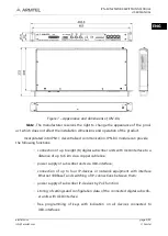
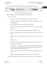
Connect the power cable to POWER socket of IPN-8U (see Figure 2), and then to
the power supply. Pin 3 of the power cable connector must be connected to the
common ground bus of the cabinet (rack). If necessary, connect the functional
grounding to the terminal located on the rear wall of the housing
5.
After the power is turned ON, the firmware is downloaded and the IPN-8U is ini-
tialized. At this time, CPU indicator is not lit.
6.
When the download is completed, CPU indicator starts flashing evenly, which
means that IPN-8U goes into operation.
In the passport, make notes about the place and time of installation of the IPN-8U.
2.4.3 Dismantle the IPN-8U in the following order:
1.
Make sure that the power supply power switch is in the off position.
2.
Disconnect the power cable from the power supply, and then from the POWER
connector.
3.
Disconnect the subscriber devices from the terminal block of the IPN-8U sub-
scriber connection cable.
4.
Disconnect the terminal block of the connection cable from the DIN rail.
5.
Disconnect the IPN-8U from the network equipment.

