IPN-8U NETWORK SWITCHING MODULE
USER MANUAL
page 10/32
armtel.com
© Armtel
ENG
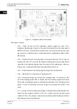
Figure 3 – Fragment of the main board
The Figure 3 shows:
−
«S3» – block of keys for PoU (phantom power) supply for each of U-
interfaces. Numbering of ports on the switch box starts from the back wall of
IPN-8U enclosure. At present the switches are not used, because power sup-
ply mode on U-interface line is controlled by the configuration data of IPN-
8U module;
−
«S2» – functional key for cleaning data. If you push and hold «S2» on the op-
erating unit, then in 5 seconds the network setting and the user data will be
returned to the default settings from the memory file «default.par». After re-
leasing «S2», automatic loading of new parameters will occur;
−
«X2» – JTAG connector for initial programming at the manufacturer;
−
«X5» − COM
-port for connection of diagnostics PC;
−
«X4» – functional jumper for coming into loading mode. If contacts of «X4»
are closed during power ON or restart, then the loading program will start.
The mode of loading program is indicated by alternate color changing of the
ports 1-4 and 5-8 indicators from red to green. At present this mode is not
used;
−
«J1» – jumper from recording, this bridge is installed at the manufacturer be-
tween the first (upper) contact of the «X1» socket and the second (lower)
contact of «X3». The jumper is removed only during initial loading of embed-
ded software at the manufacturer;

