3
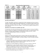
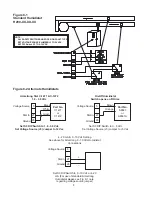
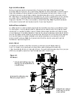
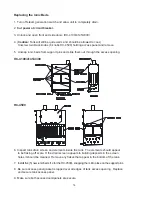
3. Site Selection. The humidifier should be installed in an easily accessible location.
Do not install the unit where malfunction of the humidifier might cause damage
to non-repairable, unreplaceable or priceless property. Refer to Installation section
for other details regarding site selection.
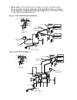
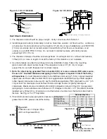
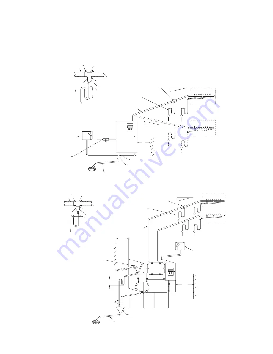
Figure 3-1 HC-4100/4145/4300 Installation
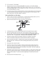
Figure 3-2 HC-4500 Installation
Hose
Clamp
Soldered
Joints
UP
To
Drain
Hose
2"
Insulated
Copper
24
Clearance
Air
Gap
1"
ID
Hose
Fused
Disconnect
or
Magnetic
Breaker
Within
Sight
of
Unit
Water
In
3/8"
Copper
Type
with
Ball
Valve
1"
Copper
(Min.)
Pitched
1"
per
12"
(Min.)
to
Open
Drain
Pitch
Min.
1"
Per
12"
Back
to
Unit
See
Detail
"A"
Pitch
Min.
1"
per
12"
Back
to
Unit
"P"
Trap
Drain
Every
20'
of
Piping
or
at
Bottom
of
Vertical
Run
Full
Size
Tee
2"
Copper
Tee
Reducer
1/2"
or
3/8"
Copper
Tube
6"
Min.
Steam
Hose
or
Copper
Detail
"A"
Hose
Clamp
Full
Size
Tee
See
Detail
"A"
Pitch
Min.
1"
per
12"
Back
to
Unit
"P"
Trap
Drain
Every
20'
of
Piping
or
at
Bottom
of
Vertical
Run
2"
Insulated
Copper
Fused
Disconnect
or
Magnetic
Breaker
within
sight
of
Unit
12"
Water
In
1/8
NPT
10"
Min.
3/4"
NPT
Pipe
Air
Gap
24"
1"
Copper
(Min.)
Pitched
1"
Per
12"
(Min.)
to
Open
Drain
Hose
1/2"
or
3/8"
Copper
Tube
Reducer
2"
Copper
Tee
Steam
Hose
Soldered
Joints
Up
To
Drain
Detail
"A"
6"
Min.


