Armstrong HumidiClean HC-4100 Series Installation, Operation And Maintenance Instructions Download Page 4

4

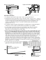
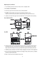
HC-4100/4145/4300 Mounting

The HumidiClean models HC-4100/4145/4300 are designed to be wall mounted.  A wall mounting
bracket and lag screws are provided for mounting on 16" (41 cm) centers.  The operating weight of
the unit is 186 lb. (84 kg).  A clearance of 24" (61 cm) on the right side and in front of the cabinet is
required for servicing.

1. Position wall mounting bracket level on wall and mark hole pattern. Make sure holes line up

with studs or other sturdy structure.

2. Use  3/8" x  1 1/2" lag screws provided to secure the bracket.

3. Hang the humidifier on the wall mounting bracket. The  weight of the unit is 112 lb. (51 kg).

The HC-4500 HumidiClean is designed to be floor mounted on a level surface. The operating weight
is 370 lb., a clearance of 24" is required for the front and sides, 12" minimum for the back.
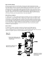
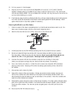
Water Fill Supply

The humidifier can use any potable or purified water supply. Water pressure must be
25-125 psi (1.7 - 8.6 bar).  Water temperature must be less than 140°F (60°C).

1. Install a shut-off valve near the unit.

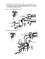
2. Connect the water supply to the 3/8" compression fitting on the fill water solenoid valve on

models HC-4100/4300, 1/8" NPT on HC-4500. The knock-out for the water supply tubing is to
the left of the fill valve in the side wall. (HC-4100/4145/4300)

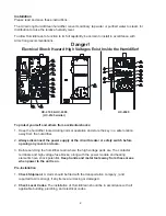
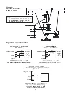
Electrical Service Wiring

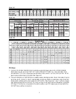
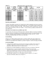
1. Connect main power supply wiring to high voltage terminals in unit. Read  breaker size

required on humidifier’s nameplate and refer to Table 6-1 and 6-2 for HC-4100/4145/4300 wire
(gage) required; Table 6-1 and 6-3 for HC-4500. Make sure an interlocking circuit breaker or
safety switch (not furnished) is accessible and within sight of the unit.

2. The humidifier cabinet must be grounded. A ground lug is provided in the cabinet.

3. Use only wire with copper conductors rated 194°F (90°C) or higher for power supply

and grounding.

Summary of Contents for HumidiClean HC-4100 Series

Page 1: ...tion 10 11 Maintenance 11 16 Troubleshooting 16 21 PC Board Switch Data 22 Typical Wiring Schematic 23 24 Repair Parts 25 31 Humidistat Data 32 35 HumidiClean Series HC 4100 4145 4300 4500 Humidifiers...

Page 2: ...n away from the humidifier 2 Always disconnect the power supply at the circuit breaker or safety switch before opening any covers or doors 3 Before servicing the humidifier learn where the high voltag...

Page 3: ...In 3 8 Copper Type with Ball Valve 1 Copper Min Pitched 1 per 12 Min to Open Drain Pitch Min 1 Per 12 Back to Unit See Detail A Pitch Min 1 per 12 Back to Unit P Trap Drain Every 20 of Piping or at Bo...

Page 4: ...ter Fill Supply The humidifier can use any potable or purified water supply Water pressure must be 25 125 psi 1 7 8 6 bar Water temperature must be less than 140 F 60 C 1 Install a shut off valve near...

Page 5: ...tput lb hr kg hr Nom Amps Three Phase Steam Output lb hr kg hr Nom Amps Three Phase Steam Output lb hr kg hr Nom Amps Three Phase Steam Output lb hr kg hr Nom Amps Three Phase Steam Output lb hr kg hr...

Page 6: ...er is required Contact the factory with questions Connect dispersion tube s to HumidiClean tank using 2 5 cm nominal insulated copper pipe and hose cuffs provided We do not suggest steam distribution...

Page 7: ...control humidistat where it will sense the average air condition of the space to be humidified Avoid areas of restricted circulation or locations where the sensor will be subjected to drafts localized...

Page 8: ...ong Stat C 1471 C 1472 1 9 3 9 Vdc Set S3 DIP Switch to 1 9 3 9 Vdc Set Voltage Source J3 Jumper to 12 Vac 5 27 28 Voltage Source Stat In Ground _ 4 20 mA 0 10 Vdc Setting See above for Armstrong 0 10...

Page 9: ...n there is insufficient air flow in a duct system A duct pressure switch is preferred as an airflow sensor The pressure switch should open on insufficient airflow opens on fault Airflow switch should...

Page 10: ...mit humidity switch is closed the heating elements will be activated and the STEAM GENERATION LED will be turned on The water fill solenoid continues to be activated until the water level in the tank...

Page 11: ...ning 10 of the service life setting When 100 of the bed life setting has been reached the Service Life LED will be on constant The unit will drain the tank and not respond to a call for humidity A Ser...

Page 12: ...left for 20 seconds until the front panel LED s illuminate and than all go off except for the POWER ON LED B Modifying the Bed Life Setting 1 Complete the steps for servicing the unit as outlined abov...

Page 13: ...ce The HumidiClean is designed to minimize maintenance As stated in the PRINCIPLE OF OPERATION section after the HumidiClean has accumulated 90 of the selected Service Life in hours of heater on time...

Page 14: ...them out through the access opening 6 Inspect tank drain screen and elements inside the tank The elements should appear to be flaking off scale If the drain screen appears to building deposits in the...

Page 15: ...nd 29 common probe from the probes noting the probe and wire locations Note Level control float switches are used for DI RO or very pure water Cleaning should not typically be required 5 Unscrew the p...

Page 16: ...ntinuity checks should be made with main power OFF Humidifier will not fill with water when power is applied 1 Make sure Steam Generation Switch is on and verify continuity at terminal block TB1 on di...

Page 17: ...electrodes the water may be too pure consult factory or if the voltage drops very slowly to about 5 volts then the electrodes need cleaning See page 15 for cleaning procedure for electrodes 2b For DI...

Page 18: ...e Humidifier runs continuously RH is well over set point 1 Verify humidistat is wired correctly and stat selector jumpers S3 J3 See Fig 9 1 and 22 1 on the PC board are set correctly for the humidista...

Page 19: ...le The voltage across EC1 10 and EC1 18 low voltage signal to power module should be 11 12 Vdc at 100 power a If no or low voltage the PC board is likely defective b If voltage is OK but green LOAD LE...

Page 20: ...ome diagnostic routines programmed into the PC board If these routines detect a problem the unit will shut down and flash the ERROR LED a certain number of times followed by a long pause 1 Blink The l...

Page 21: ...ill then flash Release the reset button and the unit should resume normal operation If the water level is above the low water the unit will drain below the low water level and refill before energizing...

Page 22: ...ge Source Supplies 5 Vdc to terminal 5 on low voltage terminal strip Voltage Source Supplies 12 Vac to terminal 5 on low voltage terminal strip Voltage Source Voltage Source J3 Parameter 24 Vac 5 Vdc...

Page 23: ...23 HC 4100 4145 4300 Series HumidiClean Typical Wiring Schematic...

Page 24: ...24 HC 4500 Wiring Schematic...

Page 25: ...Board B5072 11 Over Temperature PC Board B7115 12 Ribbon Cable B5150 13 Reset Rocker Switch Momentary A9012 14 On Off Rocker Switch A9104 15 LED Display Board B5140 Item No Water Compartment Part No...

Page 26: ...ss H1 H2 480 vac 125 across H1 H2 600 vac 194 across H1 H2 Power Tansformer secondary All Voltages 0 6 across X1 X3 0 4 across X1 X2 Power Tansformer Note All measurements should be made with the main...

Page 27: ...56 13 Reset Rocker Switch Momentary A9012 14 On Off Rocker Switch A9104 15 LED Display Board B5140 Item No Water Compartment Part No 16a Probe Level Assembly C4935 16b Float Level Assembly C4936 16c L...

Page 28: ...D3351 Component Voltage Resistance Fill Valve 24 vac 8 8 Drain Valve 24 vac 4 1 Thermocouple in Heating Element 0 51 208 240 380 Volt 30 33 5 40 45 50 3 60 kW 240 V 7 4 9 1 380 Volt 72 kW 220 V 5 2 6...

Page 29: ...1 B5044 1 240 B5047 2 B5048 2 B5043 2 B5044 2 380 B5047 1 B5048 1 B5043 1 B5044 1 480 B5047 3 B5048 3 B5043 3 B5044 3 600 B5047 4 B5048 4 B5043 4 B5044 4 Supply Voltage without TC 2 per unit with TC...

Page 30: ...30 HumidiClean Series 4500 Approximate Shipping Weight 175 lb 80 kg Maximum Operating Weight full 370 lb 172 kg EHF III Fan Package 33 lb 15 kg...

Page 31: ...team Outlet Front 12 7 8 327 J Water Supply Bottom 11 7 16 290 K Water Supply Front 1 21 32 42 L Electric Supply Side 2 1 4 57 M Electric Supply Back 14 7 32 361 N Clearance Side P Clearance Front Wei...

Page 32: ...tions Operating Conditions 5 C to 50 C 32 F to 122 F Control 0 to 95 R H non condensing Sensor 0 to 100 R H see Note 1 Resolution 0 1 Repeatability 0 5 Accuracy and sensor interchangeability 2 R H fro...

Page 33: ...m Top Autocal Button Invisible Wiring From Back Security Screw Base Cover Cover 3 1 4 83 mm 4 1 2 114 mm 3 3 4 96 mm 1 1 4 32 mm 1 1 4 32 mm 2 50 mm 1 25 mm 2 7 8 71 mm 2 7 8 71 mm 15 16 23 mm 1 5 8 4...

Page 34: ...This sensor is used to reset the humidity setpoint during the cold season to minimize condensation on windows and building structures When the outdoor temperature falls below the selected high temper...

Page 35: ...r is installed in the supply duct An outdoor temperature sensor is installed in the fresh air duct Humidistat model number H270 69 13 10 31 Figure 35 1 Alternative humidistat wiring A17898 H270 On Off...

Page 36: ...defects or any condition or use of the products supplied by Armstrong however caused and whether such claim is based upon warranty contract negligence strict liability or any other basis or theory is...

Reviews: