


0040501006 3814
Page 2-21
Operating and installation instructions
Thrust actuator ARI-PREMIO
®
-Plus 2G
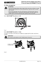
Fig. 9-C
Fig. 9-C:
- Place thrust actuator (pos. 50) on valve.
- Mount thrust actuator (pos. 50) on fitting with two
T-head bolts (pos. 50.19), two washers (pos.
50.20), two spring washers (pos. 50.21), two
hexagon nuts (pos. 50.22).
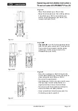
Fig. 9-D/E
Fig. 9-D/E
-
only 2,2-5 kN:
Turn the manual operating device
(pos. 50.130) with a wrench (a/f 17) and use it to
move out the thrust actuator until the driving
spindle (pos. 50.30) comes to rest on the
threaded bush (pos. 50.87).
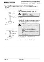
Fig. 9-F
Fig. 9-F:
- Screw the coupling (pos. 50.27) firmly into the
torsion safety feature (pos. 50.32) and secure in
place using grub screw M6 (pos. 50.35).
- Run valve to lowest position.
- Clip lift dial (pos. 50.23) onto yoke in such a way
that top edge of torsion safety feature is in
alignment with tip of arrow mark on lift dial.
- Run valve to both final positions and check to
ensure that these are safely reached
- Carry out electrical connection (see point 5.4).
- For starting up refer to point 6.0
turn