background image


M  

H  

M  

D


SET 

TYPE


If no further actions take place the  panel will  automatically return to  normal state after 

approximately 30 seconds. Otherwise at the end, press the ESC on the keypad or the Dis-Arm 

key on a registered Key Fob to return the panel to normal state.Entry Delay timer:Designated 

entry  points ( i.e. front door and may be back door ) are  subject  to an  Entry Delay Time any 

where from 1 to 255 seconds depending on time selected when configuring the system.


This delay provides a user with enough time to enter the armed  premises and disarm  the 

system before an alarm is triggered.


How To Set Entry Delay Timer: Press the PROG key on the  keypad, a series of  - - -   will 

appear on the LCD. Press the Disarm key on  any current  registered  Key Fob or entering the 

preprogrammed PIN code, and the word 'Sensor' will appear on the LCD. Pressing the  #  key 

on the  Keypad,  the  LCD  will  show the words  'SYS config'.  Press 0 then 2 on the numeric 

Keypad. 02 will  appear in the top  left  hand  corner of the LCD ( refer to  section 3. 9  for the 

configuration codes). Enter the required entry time using the configuration code,the selected 

code will be displayed in the bottom right hand corner of the LCD. Press  PROG to  store this 

number.


If no further actions take place the panel will  automatically  return to normal state  after 

approximately 30 seconds. Otherwise at the end, press Dis-Arm key on a registered  Key Fob


to return the panel to normal state.


How to allocate and set zones:  Press the PROG  key on  the Keypad, a series of - - - will 

appear on the LCD. Press the Disarm key on any current registered Key Fob or entering  the 

preprogrammed PIN code, and the word 'Sensor' will appear on the LCD. Pressing the * key 

on the Keypad,  the LCD will show the words 'Zone type', pressing No1 to 8 numeric key  to 

select  corresponding zone,  then  pressing the  0 or  1 numeric  Keypad to  configure all the 

fields in this zone. At the end, press the PROG key to complete and save operation.


By way of example, below is configured as follows:


Zone 7  selected is a Watchdog  Zone programmed  without  entry or exit  time, it's a  24 

hour .


Zone with silent when alarming, its an internal detector and  there are sensors  allocated 

to it.


Zone 7 selected


3.15 Sounder cut off time


The sounder cut off  time is the  time  permitted for the  sounder to sound  when an  alarm 

activation takes place. This can be from 1 to 1980 seconds, or do not stop until the C.s or user 

confirm it, depending on time selected when configuring the system.


Setting the sounder cut off time: Press the PROG key on the Keypad, a series of - - -   will 

appear on the LCD. Press the Disarm key on any  current registered Key Fob  or entering  the 

preprogrammed PIN code, then the word 'Sensor' will appear on the LCD. Pressing the # key 

on the  Keypad,  the LCD  will show  the words  'SYS config'.  Press 0  then 3 on the  numeric 

Keypad. 03  will  appear in  the top  left  hand  corner of the LCD  (refer to section 3.9 for the 

configuration codes).  Enter the  required  cut  off  time  using  the configuration   code.  The 

selected code will be displayed in the bottom right  hand   corner of the LCD. Press PROG to 

store this number.


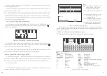
1  

2  

3  

4  

5  

6  

7


1  

1:watchdog zone  

0:not a watchdog zone


2  

1:exit delay  

0:no exit delay


3  

1:entry delay  

0:no entry delay


4  

1:24 hours zone  

0:not 24 hours zone


5  

1:sounder when alarming  

0:silent when alarming


6  

1:armed zone  

0:part armed zone


7  

1:sensor in the zone  

0:no sensor in the zone (disabled)


Figure 10: zone type configuration


17 

10


Summary of Contents for ZDAS-300

Page 1: ...Luxury Voiced LCD Alarm System USER S MANUAL Model ZDAS 300 Thank you for choosing our panel Please read the manual carefully before fixing it ...

Page 2: ......

Page 3: ...VIEW 1 1 1 Introduction 1 1 2 Basic Principle of Operation 1 1 3 Component Parts 2 1 4 Optional Extra Detectors available 2 2 DESCRIPTION 3 2 1 The Keypad 3 2 2 The LCD Character details and description 4 3 INSTALLATION INFORMATION 9 3 1 The Basic Flow Chart 6 3 2 Registering Key Fobs 7 3 3Registering Sensors 7 3 4 Installing Wired Detector 8 3 5 Checking Registration 8 3 6 Deleting Registered Key...

Page 4: ...s PROG to save using this way can set C S Account in Pry 7 or other private phone No press the registered key fob ESC key to exit To set C S phone number 1 To register Key fobs 2 To register Detectors 3 To set Zone type 4 To set System configuration 5 To set C S phone NO and site code 1 OVERVIEW 1 1 Introduction 1 Blue backup LCD display everything you want to konw about the panel 2 Full complianc...

Page 5: ...the Alarm Signals from the various Detectors It also contains the central Station communicator and By directional Audio Verification mechanism Everything you need to know about the security system is displayed on the panel keypad LCD The zones 24 Hours Armed Part armed Disarmed and the important Messages regarding system status are displayed on the LCD screen See section 2 1 and 2 2 Wireless Remot...

Page 6: ...tect the particular frequency and then transmitting an alarm signal to the control panel 1 2 3 4 5 6 7 1 1 watchdog zone 0 not a watchdog zone 2 1 exit delay 0 no exit delay 3 1 entry delay 0 no entry delay 4 1 24 hours zone 0 not 24 hours zone 5 1 sounder when alarming 0 silent when alarming 6 1 armed zone 0 part armed zone 7 1 sensor in the zone 0 no sensor in the zone Zone 1 selected 2 DESCRIPT...

Page 7: ...ng system status appear on the LCD screen LOG M D H M D 2 2 The LCD Character details and description 2 2 1 The panel LCD screen whole information shows as follows Figure 23 Detector No 2 in zone 3 is low voltage LOG DIS PART ARMED WatchDog M D H M D B When the panel is in the Armed PART Armed mode if the detector such as PIR detects itself being low voltage the panel will sound a beep every secon...

Page 8: ... is transferred to the C S the operator then has access to the customer details address name phone numbers 2 2 2 When the panel is set in the away armed mode the LCD screen will show the following ARMED key holders etc He also has audio access to the premises He can Listen in or Speak to the occupants this will allow the C S operator to request a pre arranged password to confirm the identity of th...

Page 9: ... fob will still be sounder alarm if it is set with sounder alarm 4 9 Access the Control Panel from a remote telephone mobile or land line The Remote Control enables the use of the land line phone or mobile phone to remotely control panel Call the phone number of the line connected to the alarm panel the panel will answer the call after 1 to 8 rings programmable When the panel answers the call ente...

Page 10: ...ows particular detectors in each Zone to be local alarm only or local alarm and transmit alarm information to the C S each detector can be configured differently e g local Alarm only or local Alarm and C S function door bell function or in the case of Key Fob Request Assistance with without sounder How to set the function press Sensor key and appears on the LCD Press registered Key Fob or entering...

Page 11: ...n the keypad a series of appear on the LCD Enter the PIN code or press the Disarm key on a registered key fob and the word Sensor will appear on the LCD Trigger the detector you wish to register the panel will receive the detectors code and the word CODE will appear on the LCD Pressing a numeric key 1 to 8 on the keypad will select the zone you wish to allocate the detector e g Pressing No 3 on th...

Page 12: ...e No 2 detector in Zone 3 If no further actions take place the panel will automatically return to normal state after approximately 30 seconds Otherwise at the end press Dis Arm key on a registered Key Fob to return the panel to normal state 3 8 The Zone Setting and Allocation The alarm system has 8 zones which can be configured depending on your requirements The Factory Default Zone configuration ...

Page 13: ...d PIN code and the word Sensor will appear on the LCD Pressing the key on the Keypad the LCD will show the words Zone type pressing No1 to 8 numeric key to select corresponding zone then pressing the 0 or 1 numeric Keypad to configure all the fields in this zone At the end press the PROG key to complete and save operation By way of example below is configured as follows Zone 7 selected is a Watchd...

Page 14: ...04 20 seconds 02 Entry delay time delay alarm The time is double digit XX The actual time is the product of XX times 5 The initialization value is 06 30 seconds 03 Sounder run time The time is double digit XX The actual time is the product XX times 20 The initialization value is 06 120 seconds 04 Watchdog time The unit time is hours The factory default value is 12hours 05 Watchdog start and stop t...

Page 15: ...is required within 2 5 seconds after transmitting data to the C S the Panel Will receive the SPEAK request from C S If it is not required the panel hangs up automatically ALM phone line cut_off alarm Figure15 The LCD display when the phone line is cut 13 Engineer Option Listen to dial out DTMF 0 NO 1 YES This option will Automatically extinguish when the panel is closed or on the hour Default 0 14...

Page 16: ...e account code using the numeric keypad on the panel this is normally a 4 Digit Code called site code Press Prog key to store the programmed number If no further actions take place the panel will automatically return to normal state after approximately 30 seconds Otherwise at the end press the Dis Arm key on a registered Key Fob to return the panel to normal state 3 12 Deleting Zones How To Delete...

Reviews: