MANUALE D’USO ROUTE - rev. 2 - 10/01
pag. 5/15
The maximum continuous working temperature referred to water depends on the choice of materials
(specified on the identification plate):
80 °C (176 °F)
execution WR
110 °C (230 °F)
execution GF
The ambient temperature interval is related to the choice of materials (specified on the identification plate):
0 - +40°C (14
÷
104 °F)
execution WR
-20 - +40°C (-4
÷
104 °F)
execution GF
The maximum pressure the pump may be subjected to is 1.5 times the head value developed with the outlet
closed.
The vapour pressure value of the liquid to be pumped must exceed (by at least 1m w.c) to the difference
between the absolute total head (suction side pressure added to the positive suction head, or subtracted by
the suction lift) and the pressure drops in the suction side piping (including the inlet NPSHr drops shown on
the specific tables).
The pump does not include any non return valve nor any liquid flow control or motor stop device.
5 OPERATING
PRINCIPLE
HYDRAULICALLY alike to all centrifugal pumps, it is equipped with a blade-type impeller rotating within a
fixed housing. It has a tangential outlet (or radial with an internal deflector) and, by creating a depression in
the center, it allows the liquid to flow from the central suction side. Then, flowing through the impeller's
blades, the fluid acquires energy and is conveyed towards the outlet.
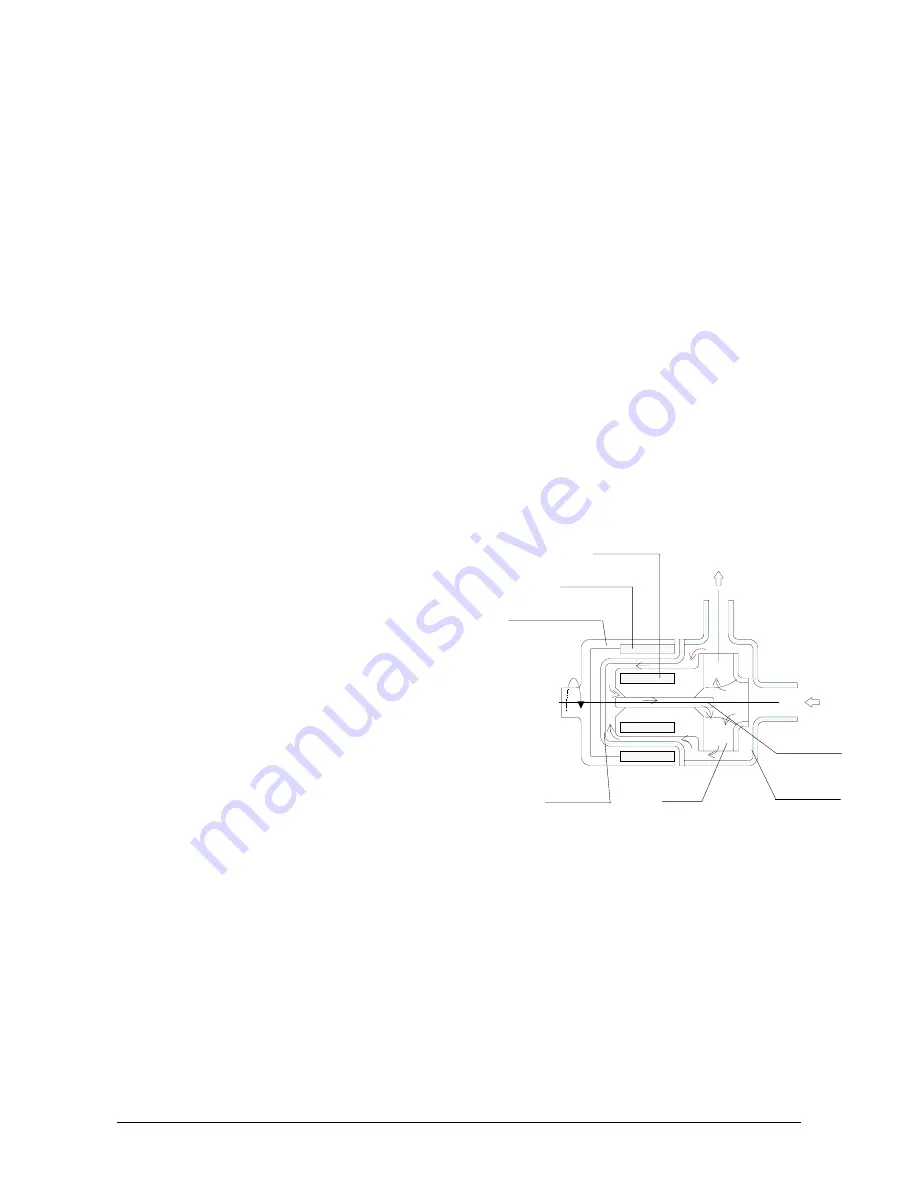
MECHANICALLY different from the traditional
centrifugal pumps in the impeller motion drive thanks
to the magnetic field created between the primary
outer magnet and the inner magnet (not visible
because housed inside the impeller hub). The
magnetic field crosses the plastic parts and the liquid,
and firmly couples the two magnet assemblies. When
the motor causes the outer magnet to rotate together
with its housing, the inner magnet assembly is
dragged at the same speed. As a result the impeller,
which is integral to it, is maintained in rotation.
The SHAFT, totally within the housing, is not involved
in the transmission of rotary motion; its only function is
to act as a centering guide and support for the
impeller. To this end the components are designed so
that a spontaneous cooling circuit (due to a simple
effect of pressure) is established to cool the surfaces
subject to friction. Periodic inspections prevent the
build-up of sediments between the shafts and the
guide bushes significantly lengthening their working
life.
motor side
outer magnet housing
outer magnet
inner magnet
outlet
inlet
pump shaft
impeller
rear casing
volute casing


