


21
WC252A
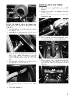
NOTE: The flex-shaft coupler must engage com-
pletely covering the majority of the splines of the
input shaft.
6. Attach the brake line support to the mounting bracket
and tighten securely.
7. Tighten the input coupler clamp cap screw to 7 ft-lb.
WC244A
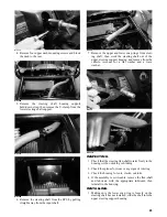
8. Install the flex-shaft clamp bracket and four cap
screws loosely installed; then install the U-clamp and
secure with two lock-nuts. Tighten the U-clamp lock
nuts to 7 ft-lb and the lower bracket cap screws to 20
ft-lb.
9. Install the upper steering flex-shaft hold-down strap
and tighten the cap screw to 50 in.-lb.
WC247A
10. Connect the two electrical connectors and check EPS
operation.
11. Install the hood and grille.
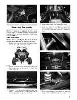
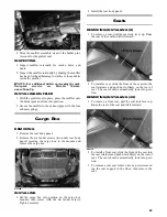
REMOVING RACK AND PINION
ASSEMBLY
1. Remove the hood and grille; then remove the EPS
assembly.
2. Remove the front differential assembly (see Drive
and Brake Systems).
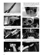
3. Remove the cotter pins and nuts securing the tie rods
to the steering rack.
WC259
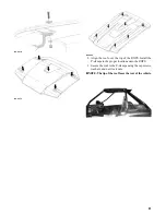
4. Remove four cap screws securing the upper mount-
ing bracket to the frame and remove the bracket.
WC278A
5. Remove four cap screws securing the rack and pin-
ion assembly to the frame; then rotate the rack and
pinion assembly to the rear and out of the frame from
either side.
WC260A