


POH / AFM
AQUILA AT01-100C
Section 7
AIRCRAFT DESCRIPTION
Document Nr.:
Issue:
Supersedes Issue:
Date:
Page:
FM-AT01-1010-103
A.08
A.06 (01.06.2018)
25.05.2020
7 - 4
Also the G500 ADC and its OAT probe are protected by a dedicated push-pull circuit breaker.
The circuit breaker is located on the right side of the instrument panel and is marked with
ADC
.
Current flows through all G500 and G500 TXi circuit breakers as soon as the
ALT1 / BAT
switch has been turned on.
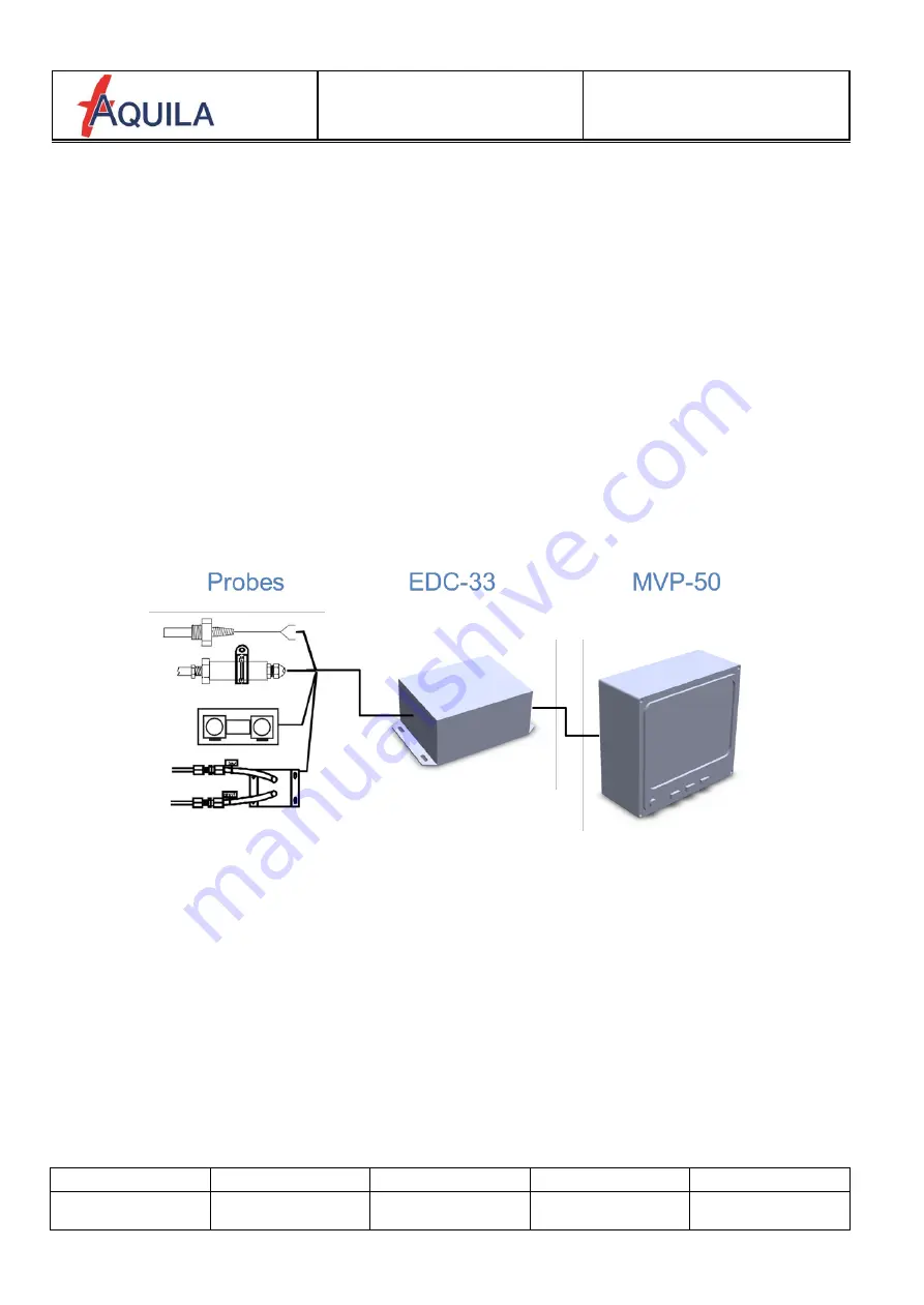
7.1.2 Glass Panel Engine Monitor MVP-50P-AQ
The MVP-50P-AQ consists of an indication / actuation interface (MVP-50), an engine data
converter (ECD-33) and the attached probes.
When engine limits are exceeded, the warning light
ENG
in the annunciator panel of the MVP-
50P-AQ will illuminate YELLOW (caution) or RED (operating limit).
The MVP-50P-AQ system is attached to the aircraft power supply via a push-pull circuit breaker
which is located on the right side of the instrument panel and is labeled
MOTOR INSTR 1
.
The MVP-50P-AQ system is organized as shown in the following illustration:


