7
- 29
3$57(&,&/2
&+$66,63$576
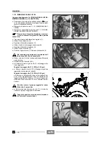
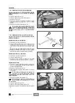
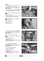
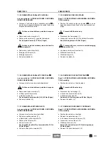
7.1.21 DESMONTAJE MANDOS / PUÑOS
Lea con cuidado 1.4 (PRECAUCIONES E INFORMA-
CIONES GENERALES).
X
+
Destornille y quite el tornillo (1) de sujeción del con-
trapeso (2).
X
Inserte la virola de una pistola dei aire comprimido en-
tre el puño (3) y el tubo mando acelerador (4) (en el
lado derecho) o tubo manillar (en el lado izquierdo)
(véase figura).
X
+
Sople el aire moviendo la virola de la pistola en sen-
tido rotatorio y en el mismo tiempo, empuñando con la
otra mano el puño (3), extraiga el mismo puño.
X
Guarde las dos arandelas (5).
Durante el reensamblaje no olvide volver a
montar ambas arandelas de deslizamiento (5).
X
+
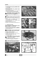
Destornille y quite los dos tornillos (6).
Durante el reensamblaje apriete con cuidado
y moderadamente los tornillos (6) en cuanto
se fijan en el material plástico.
En el lado derecho del manillar el tornillo delantero
es más corto.
X
+
Separe los dos semicascos (8-9).
Durante el reensamblaje el perno de centrado
en el semicasco inferior (9) tiene que insertar-
se en el correspondiente alojamiento del manillar.
X
Desconecte el cable acelerador (7) (en el lado izquier-
do del manillar extraiga el cable de encendido en frío).
X
Extraiga el tubo mando acelerador (4) (en el lado iz-
quierdo del manillar guarde el mando de encendido en
frío).
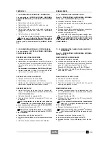
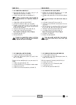
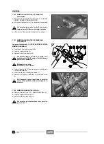
7.1.22 DESMONTAJE FARO TRASERO
Lea con cuidado 1.4 (PRECAUCIONES E INFORMA-
CIONES GENERALES).
X
Desmonte los paneles laterales, véase 7.1.4 (DES-
MONTAJE PANELES LATERALES DERECHO E IZ-
QUIERDO).
X
+
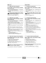
Destornille y quite la tuerca (10), guarde la arandela
y, eventualmente, el casquillo y el elemento de goma.
X
Actuando por debajo del vano portadocumentos/kit de
herramientas con una llave tubular, destornille y quite
la tuerca (11), guarde la arandela y, eventualmente el
casquillo y el elemento de goma.
X
Desplace un poco atrás el faro trasero (12).
Marque los conectores para luego volver a co-
nectarlos en la posición correcta.
X
Desconecte los conectores eléctricos.
X
Quite el faro trasero (12).
7.1.21 REMOVING THE CONTROLS/HANDGRIPS
Read 1.4 (PRECAUTIONS AND GENERAL INFORMA-
TION) carefully.
X
+
Unscrew and remove the screw (1) that fastens the
vibration-damping mass (2).
X
Insert the tip of a compressed air gun between the
handgrip (3) and the accelerator control tube (4) (on
the right side) or handlebars tube (on the left side) (see
figure).
X
+
Blow air by rotating the gun tip and at the same time
seize the handgrip (3) with the other hand and with-
draw it.
X
Take the two slide washers (5).
Upon reassembly, remember to fit the two
slide washers (5).
X
+
Unscrew and remove the two screws (6).
Upon reassembly, tighten the two screws (6)
moderately, since they are screwed onto plas-
tic material.
On the right side of the handlebars the front screw is
shorter.
X
+
Separate the two half-shells (8-9).
Upon reassembly, the centering pin on the
lower shell (9) must fit into the relevant seat
on the handlebars.
X
Disconnect the accelerator cable (7) (withdraw the
cold start cable on the left side of the handlebars).
X
Withdraw the accelerator control tube (4) (take the cold
start control on the left side of the handlebars).
7.1.22 REMOVING THE REAR LIGHT
Read 1.4 (PRECAUTIONS AND GENERAL INFORMA-
TION) carefully.
X
Remove the sides, see 7.1.4 (REMOVING THE
RIGHT AND LEFT SIDES).
X
+
Unscrew and remove the nut (10), take the washer
and if necessary the bush and the rubber element.
X
Working under the glove compartment with a socket
spanner, unscrew and remove the nut (11), take the
washer and if necessary the bush and the rubber ele-
ment.
X
Shift the rear light (12) slightly backwards.
Mark the electric connectors, in order to be
able to reconnect them in the right position.
X
Disconnect the electric connectors.
X
Remove the rear light (12).
Summary of Contents for Pegaso 650
Page 1: ......
Page 3: ...0 4 NOTE NOTES ANMERKUNGEN ...
Page 4: ...1 1 1 2 3 4 5 6 7 8 INFORMAZIONI GENERALI INFORMACIONES GENERALES GENERAL INFORMATION ...
Page 42: ......
Page 69: ...3 1 1 2 3 4 5 6 7 8 MOTORE MOTOR ENGINE ...
Page 90: ...3 22 MOTORE NOTE NOTAS NOTES ...
Page 91: ...4 1 1 2 3 4 5 SISTEMA DI ALIMENTAZIONE SISTEMA DE ALIMENTACIÓN FUEL SYSTEM ...
Page 116: ...4 26 SISTEMA DI ALIMENTAZIONE NOTE NOTAS NOTES ...
Page 117: ...5 1 1 2 3 4 5 6 7 8 IMPIANTO DI RAFFREDDAMENTO SISTEMA DE REFRIGERACIÓN COOLING SYSTEM ...
Page 130: ...5 14 IMPIANTO DI RAFFREDDAMENTO SISTEMA DE REFRIGERACIÓN COOLING SYSTEM NOTE NOTAS NOTES ...
Page 131: ...6 1 6 1 2 3 4 5 6 7 8 IMPIANTO ELETTRICO INSTALACIÓN ELÉCTRICA ELECTRICAL SYSTEM ...
Page 176: ...IMPIANTO ELETTRICO INSTALACIÓN ELÉCTRICA ELECTRICAL SYSTEM 6 46 NOTE NOTAS NOTES ...
Page 177: ...7 1 1 2 3 4 5 6 7 8 CICLISTICA PARTE CICLO CHASSIS PARTS ...
Page 226: ... 67 3 57 2 66 6 3 576 7 50 5827 3267 5 25 58 75 6 5 5 5 ...
Page 242: ... 67 3 57 2 66 6 3 576 7 66 5 12 17 5 25 5 12 17 52 5217 5 ...
Page 246: ... 67 3 57 2 66 6 3 576 7 70 5 12 3267 5 25 5 12 75 6 52 5 5 5 ...
Page 272: ... 67 3 57 2 66 6 3 576 7 96 NOTE NOTAS NOTES ...
Page 311: ...INFORMAZIONI PER LE RIPARAZIONI INFORMACIONES PARA LAS REPARACIONES REPAIRS 8 39 ...


