6
- 11
INSTALACIÓN ELÉCTRICA
ELECTRICAL SYSTEM
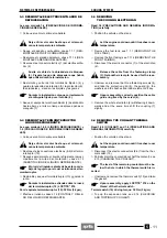
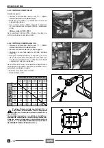
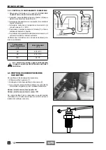
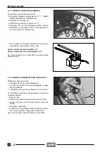
6.2.3 CONTROL DEL PICK-UP
Con el motor parado:
◆
Quite el panel izquierdo, véase 7.1.4 (DESMONTAJE
PANELES LATERALES DERECHO E IZQUIERDO).
◆
Desconecte el conector (1) y efectúe las mediciones
(en los terminales del lado pick-up).
◆
Con un tester (escala x 100
Ω
), mida la resistencia en-
tre los terminales de los cables azul marino/amarillo
(B/G) y verde/blanco (V/Bi).
Valor estándar: 150 ÷ 350
Ω
Si la resistencia es infinita (
∞
) o inferior al valor indicado,
substituya el pick-up.
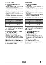
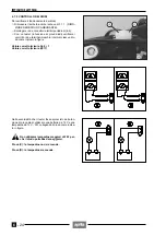
6.2.4 CONTROL DE LA CENTRALITA C.D.I.
◆
Quite el panel izquierdo, véase 7.1.4 (DESMONTAJE
PANELES LATERALES DERECHO E IZQUIERDO).
◆
Quite los enganches del conector eléctrico (2).
◆
Desconecte el conector eléctrico (2) de la centralita
C.D.I. (3).
◆
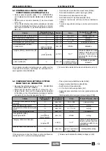
Conecte los terminales positivo (+) y negativo (–) de
un tester a todos los terminales machos que están en
el interior del conector eléctrico (2) del lado de la cen-
tralita C.D.I., comprobando la continuidad y midiendo
el valor de resistencia.
Si la continuidad y los valores de resistencia correspon-
den a aquéllos indicados en la siguiente tabla, la centrali-
ta C.D.I. puede considerarse normal.
◆
Mida la resistencia entre los terminales.
◆
Escala del tester: x k
Ω
El método de medición es aproximado, ya que
en el interior de la centralita C.D.I. hay diodos,
condensadores y otros componentes electró-
nicos.
Es aconsejable proceder con un ulterior control,
substituyendo la centralita con otra que esté seguro
que funcione, o bien, realice los controles previsto
en el capítulo 6.3 (CONTROL DE LA INSTALACIÓN
DEL CONECTOR DE LA CENTRALITA C.D.I.).
Terminal positivo (+) del tester sobre:
Az
V
Ar
N
Bi
R
Terminal negativo (-)
del tester sobre:
Az
1 -
∞
1 -
∞
1 -
∞
1 -
∞
1 -
∞
V
1 -
∞
1 -
∞
1 -
∞
1 -
∞
1 -
∞
Ar
1 -
∞
1 -
∞
∞
∞
∞
N
1 -
∞
1 -
∞
1 -
∞
1 -
∞
1 -
∞
Bi
1 -
∞
1 -
∞
1 -
∞
1 -
∞
1 -
∞
R
1 -
∞
1 -
∞
1 -
∞
1 -
∞
1 -
∞
a
6.2.3 CHECKING THE PICK-UP
With the engine switched off :
◆
Remove the left side panel, see 7.1.4 (REMOVING
THE RIGHT AND LEFT SIDES).
◆
Disconnect the connector (1) and take the measure-
ments (on the pick-up side terminals).
◆
Using a pocket tester (scale x 100
Ω
) measure the resi-
stance between the terminals of the blue/yellow (B/G)
and green/white (V/Bi) cables.
Standard value: 150 ÷ 350
Ω
If the resistance is infinite (
∞
), or lower than the prescri-
bed level, the pick-up must be changed.
6.2.4 CHECKING THE C.D.I
◆
Remove the left side panel, see 7.1.4 (REMOVING
THE RIGHT AND LEFT SIDES).
◆
Free the electric connector (2) from the couplings.
◆
Disconnect the electric connector (2) of the C.D.I. (3).
◆
Connect the positive (+) and negative (–) terminals of a
tester to all the internal male terminals of electric con-
nector (2) C.D.I. side and check the voltage continuity
and measuring the resistance value.
If the continuity and resistance values correspond to tho-
se indicated in the following table, the C.D.I. may be
considered normal.
◆
Measure the resistance between the terminals.
◆
Tester scale: x k
Ω
The C.D.I. contains diodes, condensers and
other electronic components therefore the
measuring method indicated is approximati-
ve. It is advisable to carry out a further check by re-
placing the C.D.I. with another one known to be in
perfect condition, or to carry out the checking opera-
tions indicated in chapter 6.3 (CHECKING THE
ELECTRICAL SYSTEM FROM THE C.D.I. CONNEC-
TOR).
Positive terminal (+) of the tester on:
Az
V
Ar
N
Bi
R
Negative terminal (-)
of the tester on:
Az
1 -
∞
1 -
∞
1 -
∞
1 -
∞
1 -
∞
V
1 -
∞
1 -
∞
1 -
∞
1 -
∞
1 -
∞
Ar
1 -
∞
1 -
∞
∞
∞
∞
N
1 -
∞
1 -
∞
1 -
∞
1 -
∞
1 -
∞
Bi
1 -
∞
1 -
∞
1 -
∞
1 -
∞
1 -
∞
R
1 -
∞
1 -
∞
1 -
∞
1 -
∞
1 -
∞
a
Summary of Contents for Pegaso 650
Page 1: ......
Page 3: ...0 4 NOTE NOTES ANMERKUNGEN ...
Page 4: ...1 1 1 2 3 4 5 6 7 8 INFORMAZIONI GENERALI INFORMACIONES GENERALES GENERAL INFORMATION ...
Page 42: ......
Page 69: ...3 1 1 2 3 4 5 6 7 8 MOTORE MOTOR ENGINE ...
Page 90: ...3 22 MOTORE NOTE NOTAS NOTES ...
Page 91: ...4 1 1 2 3 4 5 SISTEMA DI ALIMENTAZIONE SISTEMA DE ALIMENTACIÓN FUEL SYSTEM ...
Page 116: ...4 26 SISTEMA DI ALIMENTAZIONE NOTE NOTAS NOTES ...
Page 117: ...5 1 1 2 3 4 5 6 7 8 IMPIANTO DI RAFFREDDAMENTO SISTEMA DE REFRIGERACIÓN COOLING SYSTEM ...
Page 130: ...5 14 IMPIANTO DI RAFFREDDAMENTO SISTEMA DE REFRIGERACIÓN COOLING SYSTEM NOTE NOTAS NOTES ...
Page 131: ...6 1 6 1 2 3 4 5 6 7 8 IMPIANTO ELETTRICO INSTALACIÓN ELÉCTRICA ELECTRICAL SYSTEM ...
Page 176: ...IMPIANTO ELETTRICO INSTALACIÓN ELÉCTRICA ELECTRICAL SYSTEM 6 46 NOTE NOTAS NOTES ...
Page 177: ...7 1 1 2 3 4 5 6 7 8 CICLISTICA PARTE CICLO CHASSIS PARTS ...
Page 226: ... 67 3 57 2 66 6 3 576 7 50 5827 3267 5 25 58 75 6 5 5 5 ...
Page 242: ... 67 3 57 2 66 6 3 576 7 66 5 12 17 5 25 5 12 17 52 5217 5 ...
Page 246: ... 67 3 57 2 66 6 3 576 7 70 5 12 3267 5 25 5 12 75 6 52 5 5 5 ...
Page 272: ... 67 3 57 2 66 6 3 576 7 96 NOTE NOTAS NOTES ...
Page 311: ...INFORMAZIONI PER LE RIPARAZIONI INFORMACIONES PARA LAS REPARACIONES REPAIRS 8 39 ...

