7
- 89
3$57(&,&/2
&+$66,63$576
X
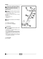
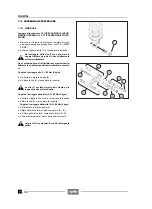
Afloje y quite la tuerca (11) y guarde la arandela.
X
Quite el tornillo (12) y guarde la arandela.
NOTA (Y)
Desde este punto en adelante, durante la ins-
talación del basculante, siga con los procedimientos
específicos, véase 7.9.4 (INSTALACION).
X
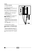
Bloquee la tuerca (13) y destornille de unos giros el
perno (14).
X
Bloquee el casquillo (13), destornille y quite el casqui-
llo de sujeción (15) con la correspondiente llave tubu-
lar, véase 1.8 (EQUIPOS ESPECIALES), guardando
luego la arandela.
X
Destornille completamente el perno.
Coloque, en la parte delantera, un soporte por
debajo del basculante y del amortiguador.
X
Extraiga el perno (14) y guarde las arandelas.
X
Quite el basculante junto con la rueda, el grupo sus-
pensión y el grupo freno.
7.9.2 SUSTITUCIÓN COJINETES
Lea con mucho cuidado 1.4 (PRECAUCIONES E IN-
FORMACIONES GENERALES).
Después de cada desmontaje controle los co-
jinetes y, si es necesario, sustitúyalos.
X
+
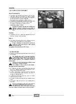
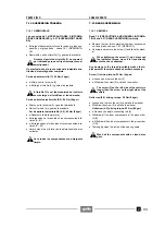
Con un trapo limpie los dos lados del alojamiento de
los cojinetes.
X
+
Quite el retén (15).
X
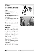
Golpear sobre una herramienta adecuada (que tenga
un diámetro igual al anillo exterior de los cojinetes)
apoyada contra el anillo exterior del cojinete (18), em-
puje hacia afuera (desde el exterior hasta el interior),
en el siguiente orden:
-
+
el casquillo (16)
-
+
el retén (17)
-
+
los cojinetes (18).
X
+
Limpie muy bien el interior del alojamiento de los co-
jinetes.
Lave todos los componentes con detergente
limpio.
X
Loosen and remove the nut (11) and take the washer.
X
Withdraw the screw (12) and take the washer.
NOTE (Y)
For the reassembly of the rear fork, from this
point onwards proceed with the specific procedures,
see 7.9.4 (REASSEMBLY).
X
Lock the bush (13) and loosen the pin (14).
X
Lock the bush (13), unscrew and remove the lock ring
(15) by means of the apposite socket spanner, see 1.8
(SPECIAL TOOLS), then take the washer.
X
Unscrew the pin completely.
Support the rear fork and of the shock absorb-
er on their front part.
X
Withdraw and remove the pin (14) and take the wash-
ers.
X
Remove the rear fork complete with wheel, suspension
unit and brake unit.
7.9.2 CHANGING THE BEARINGS
Read 1.4 (PRECAUTIONS AND GENERAL INFORMA-
TION) carefully.
The bearings must be checked and if neces-
sary changed every time they are disassem-
bled.
X
+
Clean the two sides of the bearing seat with a cloth.
X
+
Remove the seal (15).
X
Hit on an apposite punch (with diameter equal to the
outer ring of the bearings) resting on the outer ring of
the bearing (18).
X
Push out (from the outside towards the inside):
-
+
the bush (16);
-
+
the seal (17);
-
+
the bearings (18).
X
+
Thoroughly clean the inside of the bearing seat.
Wash all the components with a clean deter-
gent.
Summary of Contents for Pegaso 650
Page 1: ......
Page 3: ...0 4 NOTE NOTES ANMERKUNGEN ...
Page 4: ...1 1 1 2 3 4 5 6 7 8 INFORMAZIONI GENERALI INFORMACIONES GENERALES GENERAL INFORMATION ...
Page 42: ......
Page 69: ...3 1 1 2 3 4 5 6 7 8 MOTORE MOTOR ENGINE ...
Page 90: ...3 22 MOTORE NOTE NOTAS NOTES ...
Page 91: ...4 1 1 2 3 4 5 SISTEMA DI ALIMENTAZIONE SISTEMA DE ALIMENTACIÓN FUEL SYSTEM ...
Page 116: ...4 26 SISTEMA DI ALIMENTAZIONE NOTE NOTAS NOTES ...
Page 117: ...5 1 1 2 3 4 5 6 7 8 IMPIANTO DI RAFFREDDAMENTO SISTEMA DE REFRIGERACIÓN COOLING SYSTEM ...
Page 130: ...5 14 IMPIANTO DI RAFFREDDAMENTO SISTEMA DE REFRIGERACIÓN COOLING SYSTEM NOTE NOTAS NOTES ...
Page 131: ...6 1 6 1 2 3 4 5 6 7 8 IMPIANTO ELETTRICO INSTALACIÓN ELÉCTRICA ELECTRICAL SYSTEM ...
Page 176: ...IMPIANTO ELETTRICO INSTALACIÓN ELÉCTRICA ELECTRICAL SYSTEM 6 46 NOTE NOTAS NOTES ...
Page 177: ...7 1 1 2 3 4 5 6 7 8 CICLISTICA PARTE CICLO CHASSIS PARTS ...
Page 226: ... 67 3 57 2 66 6 3 576 7 50 5827 3267 5 25 58 75 6 5 5 5 ...
Page 242: ... 67 3 57 2 66 6 3 576 7 66 5 12 17 5 25 5 12 17 52 5217 5 ...
Page 246: ... 67 3 57 2 66 6 3 576 7 70 5 12 3267 5 25 5 12 75 6 52 5 5 5 ...
Page 272: ... 67 3 57 2 66 6 3 576 7 96 NOTE NOTAS NOTES ...
Page 311: ...INFORMAZIONI PER LE RIPARAZIONI INFORMACIONES PARA LAS REPARACIONES REPAIRS 8 39 ...


