6
- 9
INSTALACIÓN ELÉCTRICA
ELECTRICAL SYSTEM
6.2 SISTEMA DE ENCENDIDO
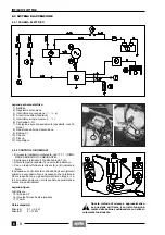
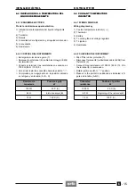
6.2.1 ESQUEMA ELÉCTRICO
Pie de la ilustración del esquema eléctrico
1) Batería
2) Regulador de tensión
3) Interruptor de encendido (
n
-
m
-
s
)
4) A los servicios auxiliares (faros)
5) Interruptor de parada del motor
(
n
-
m
)
6) Centralita C.D.I.
7) A la lógica de seguridad del arranque (caballete, pa-
lanca de embrague)
8) Resistencia anticipo de encendido
9) Bobina AT
10) Cilindro
11) Pick up
12) Generador
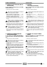
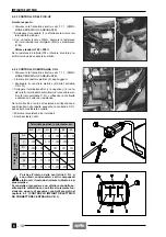
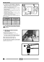
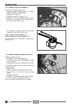
6.2.2 CONTROL DE LA BOBINA AT
◆
Desmonte el depósito de combustible, véase 7.1.1
(DESMONTAJE DEPOSITO COMBUSTIBLE).
◆
Desconecte el terminal (13) de la bobina AT (9).
◆
Extraiga el tapón de la bujía (14) y quítele el cable.
◆
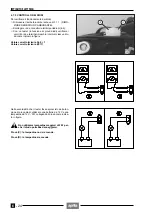
Con un tester, efectúe las mediciones (A) y (B) indica-
das en la figura.
Es necesario controlar la continuidad de los bobinados
primario y secundario.
No es necesario que la lectura en Ohm sea exacta, pero
si los bobinados están íntregos, los valores de resisten-
cia deben corresponder aproximadamente a aquéllos in-
dicados.
Pie de la ilustración figura
A-B) Mediciones
15) Bobina AT
16) Núcleo ferroso bobina (masa)
17) Tester
Valores estándares:
Medición A :
0,1
÷
0,4
Ω
Medición B :
6
÷
12 k
Ω
Este método de medición es aproximado; si
es posible, compruebe el funcionamiento co-
rrecto de la bobina substituyéndola con otra
que esté seguro que funcione.
a
6.2 IGNITION SYSTEM
6.2.1 WIRING DIAGRAM
Wiring diagram key
1) Battery
2) Voltage regulator
3) Ignition switch (
n
-
m
-
s
)
4) To the auxiliary equipment (lights)
5) Engine stop switch (
n
-
m
)
6) C.D.I.
7) To the starting safety logic (stand, clutch lever)
8) Spark advance resistance
9) H.V. coil
10) Cylinder
11) Pick-up
12) Generator
6.2.2 CHECKING THE H.V. COIL
◆
Remove fuel tank, see 7.1.1 (REMOVING THE
FUEL TANK).
◆
Disconnect the terminal (13) from the H.V. coil (9).
◆
Slip off the spark plug cap (14) and disconnect it from
cable.
◆
Measure the values of (A) and (B) indicated in the figu-
re by means of a pocket tester.
It is important to check the continuity of the primary and
secondary windings.
The reading in Ohms does not necessarily have to be ex-
act but if the windings are sound, the resistance values
must correspond approximately with those indicated.
Figure key
A-B Measurements
15) H.V.coil
16) Iron core of coil (earth)
17) Tester
Standard values:
Measurement A : 0,1
÷
0,4
Ω
Measurement B : 6
÷
12 k
Ω
This measuring method is approximate; if
possible, check the correct operation of the
coil by replacing the same with another one
which surely works.
a
Summary of Contents for Pegaso 650
Page 1: ......
Page 3: ...0 4 NOTE NOTES ANMERKUNGEN ...
Page 4: ...1 1 1 2 3 4 5 6 7 8 INFORMAZIONI GENERALI INFORMACIONES GENERALES GENERAL INFORMATION ...
Page 42: ......
Page 69: ...3 1 1 2 3 4 5 6 7 8 MOTORE MOTOR ENGINE ...
Page 90: ...3 22 MOTORE NOTE NOTAS NOTES ...
Page 91: ...4 1 1 2 3 4 5 SISTEMA DI ALIMENTAZIONE SISTEMA DE ALIMENTACIÓN FUEL SYSTEM ...
Page 116: ...4 26 SISTEMA DI ALIMENTAZIONE NOTE NOTAS NOTES ...
Page 117: ...5 1 1 2 3 4 5 6 7 8 IMPIANTO DI RAFFREDDAMENTO SISTEMA DE REFRIGERACIÓN COOLING SYSTEM ...
Page 130: ...5 14 IMPIANTO DI RAFFREDDAMENTO SISTEMA DE REFRIGERACIÓN COOLING SYSTEM NOTE NOTAS NOTES ...
Page 131: ...6 1 6 1 2 3 4 5 6 7 8 IMPIANTO ELETTRICO INSTALACIÓN ELÉCTRICA ELECTRICAL SYSTEM ...
Page 176: ...IMPIANTO ELETTRICO INSTALACIÓN ELÉCTRICA ELECTRICAL SYSTEM 6 46 NOTE NOTAS NOTES ...
Page 177: ...7 1 1 2 3 4 5 6 7 8 CICLISTICA PARTE CICLO CHASSIS PARTS ...
Page 226: ... 67 3 57 2 66 6 3 576 7 50 5827 3267 5 25 58 75 6 5 5 5 ...
Page 242: ... 67 3 57 2 66 6 3 576 7 66 5 12 17 5 25 5 12 17 52 5217 5 ...
Page 246: ... 67 3 57 2 66 6 3 576 7 70 5 12 3267 5 25 5 12 75 6 52 5 5 5 ...
Page 272: ... 67 3 57 2 66 6 3 576 7 96 NOTE NOTAS NOTES ...
Page 311: ...INFORMAZIONI PER LE RIPARAZIONI INFORMACIONES PARA LAS REPARACIONES REPAIRS 8 39 ...


