6
- 27
INSTALACIÓN ELÉCTRICA
ELECTRICAL SYSTEM
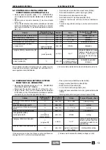
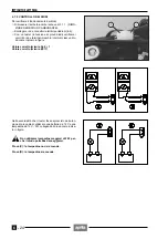
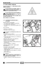
6.8 CIRCUITO NIVEL COMBUSTIBLE
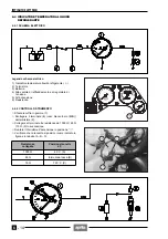
6.8.1 ESQUEMA ELECTRICO
Pie de la ilustración esquema eléctrico
1) Luz testigo reserva combustible (
g
)
(color amarillo ámbar)
2) Sonda nivel combustible
3) Batería
4) Interruptor de encendido (
n
-
m
-
s
)
5) Al regulador de tensión
6) Al encendido
6.8.2 INDICADOR NIVEL COMBUSTIBLE
◆
Desconecte el conector eléctrico (8) de la sonda nivel
combustible (2).
Control funcionamiento luz testigo reserva combusti-
ble
◆
Conecte directamente (resistencia 0
Ω
) los cables na-
ranja/negro (Ar/N) y azul marino (B) del conector (8)
(lado conjunto de cables); compruebe que la luz testi-
go reserva combustible se encienda.
Entre los cables
Resistencia
Indicación
correcta
naranja/negro (Ar/N) -
azul marino (B)
0
Ω
luz testigo
encendida
6.8 FUEL LEVEL CIRCUIT
6.8.1 WIRING DIAGRAM
Wiring diagram key
1) Fuel reserve warning light (
g
) (amber yellow)
2) Fuel level gauge unit
3) Battery
4) Ignition switch (
n
-
m
-
s
)
5) To voltage regulator
6) To ignition
6.8.2 FUEL LEVEL INDICATOR
◆
Disconnect the electrical connector (8) from the fuel
level gauge unit (2).
Checking the operation of the low fuel warning light
◆
Directly connect (resistance 0
Ω
) the orange/black
(Ar/N) and blue (B) cables of the connector (8) (har-
ness side); make sure that the low fuel warning light
comes on.
Between cables
Resistance
Correct
indication
orange/black (Ar/N) -
blue (B)
0
Ω
warning light
on
Summary of Contents for Pegaso 650
Page 1: ......
Page 3: ...0 4 NOTE NOTES ANMERKUNGEN ...
Page 4: ...1 1 1 2 3 4 5 6 7 8 INFORMAZIONI GENERALI INFORMACIONES GENERALES GENERAL INFORMATION ...
Page 42: ......
Page 69: ...3 1 1 2 3 4 5 6 7 8 MOTORE MOTOR ENGINE ...
Page 90: ...3 22 MOTORE NOTE NOTAS NOTES ...
Page 91: ...4 1 1 2 3 4 5 SISTEMA DI ALIMENTAZIONE SISTEMA DE ALIMENTACIÓN FUEL SYSTEM ...
Page 116: ...4 26 SISTEMA DI ALIMENTAZIONE NOTE NOTAS NOTES ...
Page 117: ...5 1 1 2 3 4 5 6 7 8 IMPIANTO DI RAFFREDDAMENTO SISTEMA DE REFRIGERACIÓN COOLING SYSTEM ...
Page 130: ...5 14 IMPIANTO DI RAFFREDDAMENTO SISTEMA DE REFRIGERACIÓN COOLING SYSTEM NOTE NOTAS NOTES ...
Page 131: ...6 1 6 1 2 3 4 5 6 7 8 IMPIANTO ELETTRICO INSTALACIÓN ELÉCTRICA ELECTRICAL SYSTEM ...
Page 176: ...IMPIANTO ELETTRICO INSTALACIÓN ELÉCTRICA ELECTRICAL SYSTEM 6 46 NOTE NOTAS NOTES ...
Page 177: ...7 1 1 2 3 4 5 6 7 8 CICLISTICA PARTE CICLO CHASSIS PARTS ...
Page 226: ... 67 3 57 2 66 6 3 576 7 50 5827 3267 5 25 58 75 6 5 5 5 ...
Page 242: ... 67 3 57 2 66 6 3 576 7 66 5 12 17 5 25 5 12 17 52 5217 5 ...
Page 246: ... 67 3 57 2 66 6 3 576 7 70 5 12 3267 5 25 5 12 75 6 52 5 5 5 ...
Page 272: ... 67 3 57 2 66 6 3 576 7 96 NOTE NOTAS NOTES ...
Page 311: ...INFORMAZIONI PER LE RIPARAZIONI INFORMACIONES PARA LAS REPARACIONES REPAIRS 8 39 ...

