Anthony Lifgtates, Inc.
42
MRT Models
www.anthonyliftgates.com
800-482-0003
7.2 Maintenance And Troubleshooting
Procedures
7.2.1 Check Lowering Valve Cartridge And Coil
1. Place the platform on the ground in the open position.
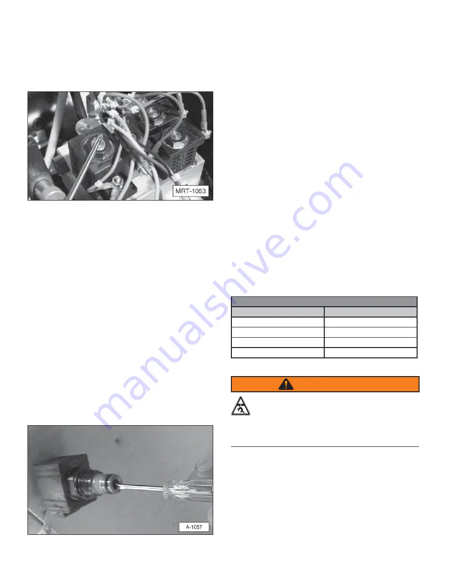
2. Place a steel screwdriver over the top of the lowering
valve cartridge coil.
3. Momentarily activate the control switch in the
DOWN position. The screwdriver should be attracted
to the magnetic field created by the coil.
4. If there is no magnetism, determine if there is power
from the control switch to the coil. If there is no
power, determine if the switch is bad or if the problem
is in the wire from the switch to the coil. If there
is power to the coil, but it has no magnetism, then
the coil is bad and should be replaced. If the coil is
good, check the lowering valve cartridge for proper
operation.
5. Remove the coil from the lowering valve cartridge
assembly.
6. Remove the lowering valve cartridge from the pump
body.
7. Clean the lowering valve cartridge and blow it dry with
compressed air (not greater than 30 psi). Also, blow
out the pump body.
8. Use a small screwdriver and carefully press on the
poppet inside the lowering valve cartridge. The
poppet is spring loaded and should move when it
is pressed. If the poppet does not move, then the
lowering valve cartridge should be replaced.
7.2.2 Inspect Cylinder Piston Seals
Inspect the cylinder piston rod seals for drifting, caused by
seal leakage.
1. Remove the breather hose, if equipped.
2. Raise the platform all the way up and hold the switch
in the “ON” position while checking for oil coming out
of the breather port to the cylinder.
3. If a continuous flow of oil comes out of this port,
while the platform is all the way up and the switch is
held “ON”, then the piston seals are leaking and the
cylinder should be replaced.
7.2.3 Checking System Pressure
Power down models have two relief valve settings; one
for raising the platform (power up) and one for lowering
the platform (power down).
To check the “power up” pressure setting:
1. Place the liftgate on the ground and remove the
pressure hose from the power up port of the pump.
2. Install a tee (customer supplied) into the power up
port.
3. Connect a pressure gauge and reconnect the
hydraulic hose.
The pressure gauge must be rated above the maximum
pressure of the liftgate. For example, use a 4000 psi
pressure gauge on a 3000 psi maximum capacity liftgate.
Low Pressure Threshold Chart
Model
Low Pressure Threshold
MRT-3500
1500 psi
MRT-4500
1700 psi
MRT-5500
2000 psi
MRT-6500
2400 psi
WARNING
CRUSH HAZARD
Do not stand or work in the platform’s work
area while operating the liftgate. Place the
pressure gauge so it can be read while operating the
liftgate from a safe location. Serious injury or death
could result if this action is not followed.
4. Raise the liftgate and check the pressure.
5. If the appropriate pressure cannot be reached,
replace the pump.
6. Check the power down relief valve pressure in the
same way as the gravity down system by installing a
tee and gauge.
7. The power-down pressure should not exceed 500 psi.


