MRT Models
21
Anthony Lifgtates, Inc.
800-482-0003
www.anthonyliftgates.com
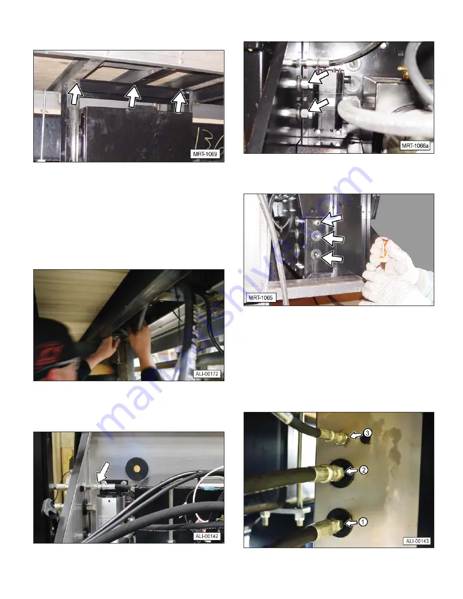
5. Use 1/4 inch welds to weld the hanger channel to all
chassis crossmembers or a minimum of three trailer
crossmembers and add any necessary bracing.
4.8.3 Make the Hydraulic Connections
Three hydraulic hoses and one breather hose run from
the liftgate to the power unit enclosure.
1. Route the street side high-pressure hose, low-
pressure hose, and electrical wire through or under
the crossmembers and along the frame to the power
unit. Also route the curbside hoses and wire to the
power unit.
2. Remove the cap from the fitting and the plug from
hose. Connect the hose to the fitting and tighten it
securely.
3. Remove the two caps from the flow divider, indicated
by the arrows.
4. Remove the plugs from the end of each hydraulic
hose.
Note
: This unit has been hydraulically tested at the
factory and the hoses are fi lled with oil. Take care
when removing the plugs not to drain oil from the
hoses, as this will create an air bubble within the
hose.
5. Insert hoses (1 and 2) through the rubber grommets
and connect them to the flow divider. Tighten the
fittings securely. It does not matter how the hoses
are attached, either hose can be connected to either
fitting.


