MRT Models
27
Anthony Lifgtates, Inc.
800-482-0003
www.anthonyliftgates.com
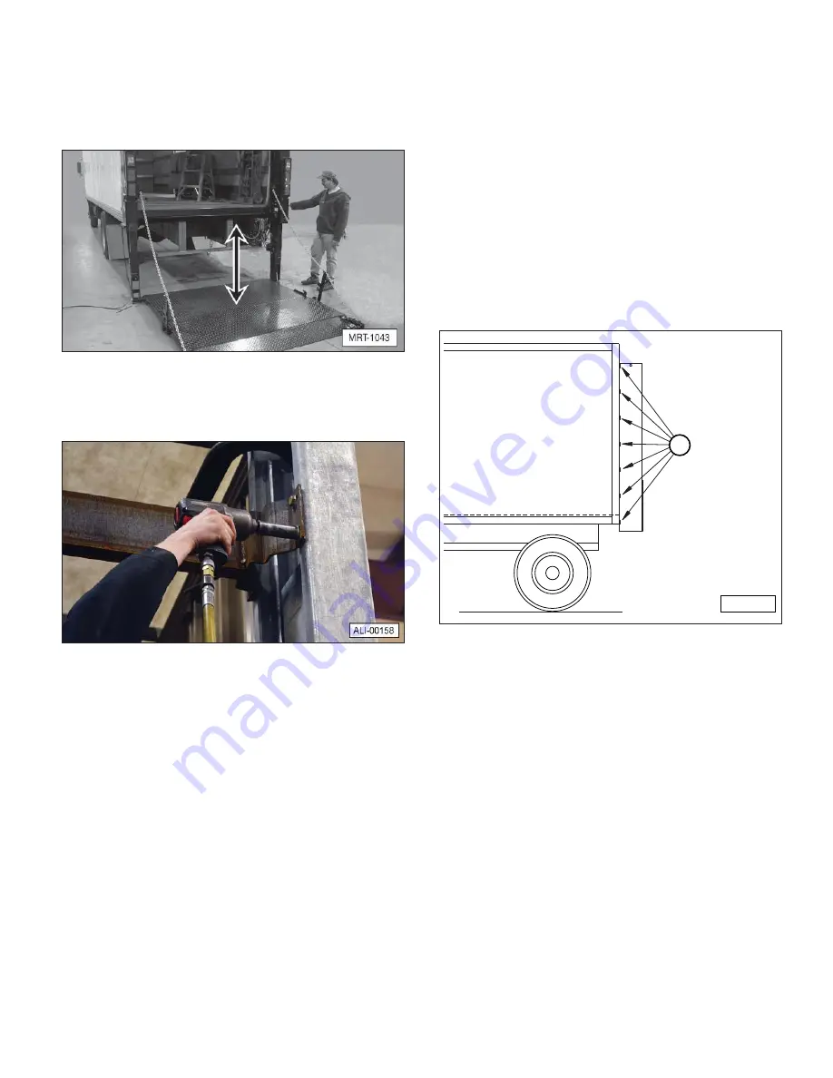
6. Raise and lower the platform to make sure it operates
without binding. Air introduced into the system during
installation will work itself out after several cycles of
normal operaton. To bleed air out of the cylinders,
refer to “4.12 Air Bleeding Procedure For MRT
Liftgates (Gravity Down Models ONLY!)” on page
30.
7. If the liftgate has been successfully operated through
its cycle, remove and discard the upper shipping
support.
4.8.6 Complete The Final Welding
1. Thoroughly check the position of the liftgate assembly
before starting the final welding.
a. The liftgate must be centered on the chassis or
trailer.
b. The crossmember must be flush with the floor.
c. Both columns must be tight against the rear frame.
d. The columns must be square with the vehicle body
and parallel to each other.
If any of these items is not correct, reposition the liftgate.
2. Weld the liftgate columns to the rear frame of the
chassis or trailer using seven, equally spaced 3/16”
wide by 2” long welds (A) down both sides (inside and
outside) of each column (28 total welds).
A
MRT-1006
Tip: Do not over weld the outside of the columns,
because too much heat can damage the hoses and
wires inside the columns.


