RECHARGE
For continued protection, the CHECKFIRE MP-N Detection and
Actuation System and the fire suppression system must be
recharged immediately after operation.
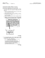
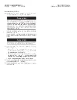
1. Loosen screws and remove cover from control module.
2. Remove battery module from enclosure and properly discard.
Battery must be replaced after each discharge.
3. Remove the empty LT-10-R cartridge from the manual actua-
tor or the automatic gas motor.
4. If system was manually actuated – skip steps 5-6, and
proceed to step 7.
5. If system was automatically actuated – remove the empty
LT-10-R cartridge from the gas motor actuator. Do not install
cartridge at this time.
6. Unscrew threaded connector on top of gas motor actuator.
Replace gas motor and clean and lubricate actuator by
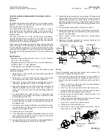
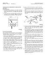
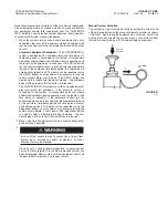
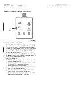
completing the following steps: See Figure 42.
a. Loosen allen head set screw which is locking gas motor
onto gas motor actuator. Use 3/32 in. allen wrench.
b. Unscrew discharged gas motor and discard.
NOTICE
When gas motor is removed, puncture pin
may pop up, out of actuator body.
c. Remove puncture pin and spring from actuator body. It may
be necessary to push pin from bottom to overcome ʻʻOʼʼ ring
friction.
d. Clean inside of actuator with a dry, soft cloth. Also, lubricate
ʻʻOʼʼ ring with a good grade of silicone grease.
e. Reinstall spring and puncture pin in actuator body. Push pin
down until bottom of pin is flush with bottom of actuator
body.
f. Thread new gas motor, Part No. 416756, unto top of actua-
tor and secure with allen head set screw.
Note: For proper
assembly, the new gas motor must be threaded fully, 6
threads, onto the actuator body and properly secured
with the allen head set screw.
NOTICE
When gas motor is installed onto actuator
body, bottom of puncture pin must be flush
with bottom of body, ± 1/16 in. (1.6 mm).
g. Reattach thread connector to gas motor thread. Hand tighten.
FIGURE 42
003945
7. Disconnect detection wire (or thermal detector leads) from the
control module as follows:
a. Loosen screws at terminals 3 and 4 of detection/output
module.
b. Loosen strain reliefs on detection wire.
c. Slide the detection wire (or thermal detector leads) out of
the control module.
d. If damaged, remove entire length of detection wire (or
thermal detector leads), cutting cable ties at points of
securement.
e. If thermal detectors are used, remove and replace any that
are damaged.
8. If detection wire is used, install an entire new length by refer-
ring to Detection Wire Routing, Pages 14-16.
9. If spot detectors are used, install any replacement detectors
and all interconnecting wire by referring to Thermal Detector
Installation, Pages 16-17. If pneumatic/linear tubing is used,
refer to instructions included with shipping assembly.
10. Reset any auxiliary shutdown or alarm equipment in accor-
dance with manufacturerʼs instructions
11. Install new battery, Part No. 427308, in module. Refer to New
Battery Installation, Page 19. Record date of installation.
12. Recharge the fire suppression system in accordance with the
corresponding manual.
13. Test the system and place into service by completing the
procedures on Pages 21 through 24 (Function Test, and
Placing the System in Service).
14. Record date of recharge on a tag or in permanent record file.
Notify operating personnel that the system is back in service.
RECHARGE
PAGE 26
REV. 02 2012-MAY-18
CHECKFIRE MP-N Electric
Detection and Actuation System Manual
PUNCTURE
PIN
SPRING
ACTUATOR
BODY
GAS MOTOR
ASSEMBLY AND
CONNECTOR
FLUSH WITH BOTTOM
EDGE OF ACTUATOR
BODY ± 1/16 IN. (1.6 mm)

