
CONTROL MODULE WIRING/DETECTION WIRE ROUTING
(Continued)
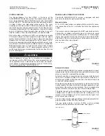
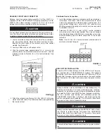
Wiring (Continued)
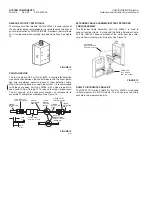
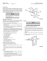
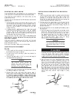
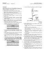
2. Route the detection wire through a strain relief at the bottom
of the MP-N control module, to the terminal strip in the control
module. Make certain wire is not exposed to damage. See
Figure 27.
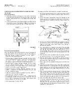
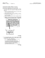
3. On the terminal block at the control module, install the wires to
terminals No. 3 and 4. See Figure 27.
Note:
It is not necessary
to be concerned about polarity when installing these wires.
FIGURE 27
002765
Thermal Detector Installation
When installing the ANSUL spot detectors, use only components
approved by ANSUL. These components consist of the following:
– Mounting Bracket Shipping Assembly, Part No. 416221 –
Consists of one mounting bracket.
– Detector Clamp Package Shipping Assembly, Part No. 416214
(for use with protective tubing) – Consists of (2) cable clamps,
(2) 1/4-20 x 1/2 in. socket head screws, (4) flatwashers,
(2) spacers, and (2) 1/4-20 x 5/8 in. socket head screws.
– Detector Clamp Package Shipping Assembly, Part No. 416762
(for use without protective tubing) – Consists of (2) cable
clamps, (2) 1/4-20 x 1/2 in. socket head screws, (4) flatwashers,
and (2) 1/4-20 x 5/8 in. socket head screws.
– Detector Connector Package Shipping Assembly, Part No.
416213 – Consists of (2) connector housings, (6) pins, and
(2) heat shrinkable sleeves.
– Protective Tubing Shipping Assembly, Part No. 416215 –
Consists of 100 ft (30.5 m) of tubing.
– Multi-Conductor Cable, Part No. 417055 – Cable must be
purchased by installer and must have a temperature rating of
392 °F (220 °C) minimum, 16-18 gauge, two conductor with
drain, minimum O.D. of 0.230 in. (5.8 mm).
– AMP crimping tool, Part No. 416784.
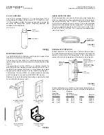
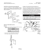
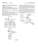
To properly install the thermal detector, complete the following:
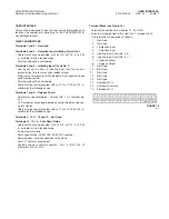
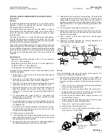
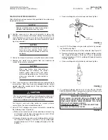
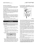
1. Secure the mounting bracket(s) near the hazard. Make certain
the bracket does not shield the detector from the heat or
flame.
2. Attach the correct temperature range spot detector to the
bracket using (2) two flatwashers and (2) two 1/4-20 x 5/8 in.
socket head screws supplied in detector clamp package. See
Figure 28.
FIGURE 28
000875
3. Starting at the ANSUL CHECKFIRE Control Module, measure
and route the cable to the first detector.
Note:
If protective
tubing is to be used, make certain cable is run through it
between each detector.
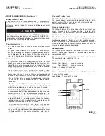
4. The circuit cable is 3 conductor. It consists of two insulated
wires and one bare ground wire. Cut all wires equal in length
and strip the outer jacket and inner sheath back 1 1/4 in.
(32 mm).
Note:
Make certain not to cut into the insulation on
the two insulated wires or cut into the bare ground wire. See
Figure 28.
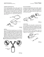
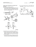
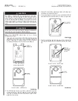
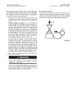
5. With the outer jacket and sheath cut back, strip the insulation
on the two inner wires 1/4 in. (6 mm). See Figure 29.
6. Slide the rubber sleeves from the AMP connector over the 3
wires. The small end of the sleeves must be toward the striped
end of the wires. See Figure 29.
7. Slide a piece of heat shrinkable tubing onto the cable. See
Figure 29.
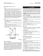
8. Crimp the pins onto all three wires, using AMP crimping tool,
AMP part No. 90277-1. See Figure 29. This tool is required for
proper crimping. It can be purchased through your local elec-
tronics distributor or is available through ANSUL as Part No.
416784.
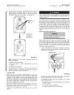
9. Press the pins into the connector housing. The two insulated
wires go into holes 2 and 3 and the bare ground wire goes into
hole 1. Make certain each locks into place. The bare ground
wire must go into hole 1 but it makes no difference which of
the two insulated wires goes into hole 2 or 3. See Figure 29.
10. Press the rubber sleeves into the connector holes.
11. Fit the heat shrinkable tubing over the connector so it covers
approximately 3/8 in. to 1/2 in. (9 mm to 13 mm) of the
connector. Heat the tubing with an approved heat gun, shrink-
ing the tubing onto the connector and cable to form a tight,
waterproof fit. See Figure 29.
INSTALLATION
PAGE 16
REV. 02 2012-MAY-18
CHECKFIRE MP-N Electric
Detection and Actuation System Manual
CABLE
CLAMP
PROTECTIVE
SLEEVE
SHRINK
TUBING
1/4-20 x 1/2 IN.
SOCKET HEAD
SCREW
1/4-20 x 5/8 IN.
SOCKET HEAD
SCREW (2)
MOUNTING
BRACKET
SPOT
DETECTOR
RUBBER
SLEEVES
PINS
DETECTION
CIRCUIT
3 4


