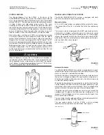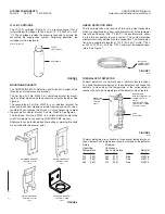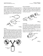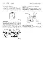
PNEUMATIC/LINEAR DETECTOR
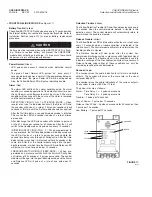
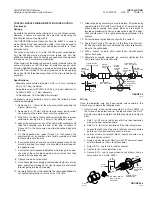
The pneumatic/linear detector, Part No. 416113, consists of 35 ft
(10.7 m) of gas filled stainless steel tubing connected to a small
pressure responder. When the gas in the tubing heats up, the
increase in pressure operates the responder, thus closing the
detection circuit of the control module. The pneumatic/linear
detector will operate at a temperature of 900 °F (482 °C) over
12 in. (31 cm) or 300 °F (149 °C) over the total length. The detec-
tor assembly connects to the control module by means of a
special wire assembly which is supplied with the detector assem-
bly. See Figure 9.
FIGURE 9
000857
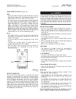
BATTERY
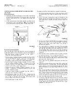
The CHECKFIRE MP-N control module uses one 3.6 VDC lithium
battery, Part No. 427308. All power required to run the detection
system can be provided from this battery. The battery is supplied
with two separate plug-in connectors. One connector is used for
plugging into MP-N modules and the other connector is used for
plugging into SC-N modules. CAUTION: Do not cut off unused
connector assembly. It must remain on battery module even
though it is not used. Simply tuck the extra connector assembly
along side the battery module when installing the cover. The
battery must be replaced annually, after discharge, or when the
YELLOW Battery LED and the Audio Alarm are pulsing. Refer to
Installation Section (page 19), New Battery Installation, for proper
battery replacement procedures. See Figure 10.
FIGURE 10
004877
END-OF-LINE RESISTOR
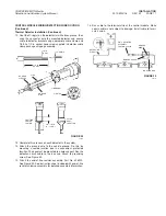
The End-Of-Line Resistor Assembly, Part No. 426520, is required
for supervision of the external input circuits. The end-of-line resis-
tor assembly is available in a package of 10, Part No. 426461.
Each package consists of 10 of the required components to
assemble 10 of the resistor assemblies. See Figure 11. The
package contains an instruction sheet, Part No. 423542, detailing
the assembly requirements.
FIGURE 11
003050
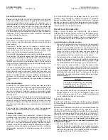
CHECK VALVE
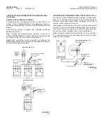
The 1/4 in. check valve, Part No. 25627, is installed in the actua-
tion line between the manual/automatic actuator and the pneu-
matic actuator on the connected fire suppression system. This
check valve allows actuation pressure to flow to the fire suppres-
sion system, but does not allow pressure from other actuation
devices to back up into the manual/automatic actuator of the
CHECKFIRE MP-N system. See Figure 12.
Other actuation devices in the fire suppression system also
require check valves to be installed in the same fashion. This
prevents pressure from escaping through an actuator whose
cartridge was inadvertently removed.
FIGURE 12
000899
SYSTEM COMPONENTS
2012-MAY-18 REV. 02 PAGE 5
CHECKFIRE MP-N Electric
Detection and Actuation System Manual
1 5/8 IN.
(4.1 cm)
1/4 IN. NPT
(BOTH ENDS)
DETECTOR
TUBE
CONNECTION TO
CONTROL MODULE
RESPONDER
LOCK
NUT
STRAIN RELIEF
CONNECTOR
CAP
TERMINAL BLOCK
WITH 4.7 K OHM
RESISTOR
SC-N
CONNECTOR
MP-N
CONNECTOR
NOTE:
DO NOT CUT OFF
UNUSED WIRE
ASSEMBLY


