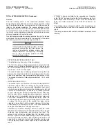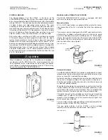
MOUNTING THE CONTROL MODULE
The CHECKFIRE MP-N Control Module can be mounted to either
a flat, rigid surface or utilizing one of the three bracket options.
If mounting the control module to a flat, rigid surface, use the
appropriate fasteners.
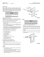
If mounting the control module to the MP-N bracket, complete the
following steps:
1. With the bracket securely mounted, position the holes in the
control module mounting flanges over the threaded studs on
the bracket. Using the supplied mounting hardware, securely
fasten the control module to the bracket with four lock
washers and nuts.
2. If utilizing the MP retrofit bracket, first fasten the retrofit
bracket onto the existing MP bracket by using the supplied
fasteners. With the MP retrofit bracket securely fastened,
position the holes in the control module mounting flanges over
the threaded studs and securely fasten.
Remove the cover from the control module.
If the internal 3.6
VDC battery is in place, disconnect the wire plug until the
field wiring is complete.
If the strain relief(s) and plug(s) are not in place, coat the male
threads with Dow Corning 737 RTV Sealant or equal and install in
holes of module back box.
At this point, the external field wiring can be installed.
GAS MOTOR ACTUATOR ASSEMBLY
Mounting
1. The gas motor must be mounted in a location where it will not
be subjected to damage or corrosion.
2. The gas motor can be mounting in either the horizontal or
vertical position.
3. It must be mounted within 10 ft (3.1 m) linear cable length of
the CHECKFIRE Control Module.
NOTICE
After automatic system actuation, the
internal gas motor device must be
replaced. Make certain assembly is
mounted in an accessible location.
4. Securely mount the actuator bracket, Part No. 54923, either
by welding or bolting to a rigid surface.
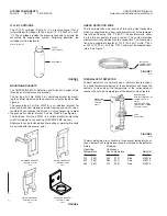
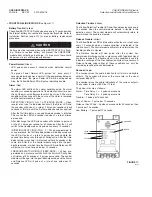
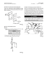
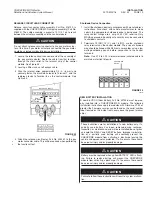
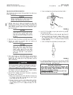
5. Remove locknut from gas motor body, position body in
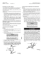
bracket hole and reinstall locknut. Wrench tighten. See Figure
24.
Note: For proper installation, make certain the gas
motor is threaded fully, 6 threads, onto the actuator body
and properly secured with the allen head set screw.
FIGURE 24
003925
CONTROL MODULE WIRING/DETECTION WIRE ROUTING
Mounting
1. Using the system layout sketch, investigate each point where
the wire will be secured to the vehicle. Keep in mind all the
guidelines in the System Planning Section. Do this on a
vehicle that has been operated recently to avoid securing the
wire too close to extremely hot components.
2. After the vehicle has cooled, loosely route the wire from the
start of the hazard throughout the proposed path through the
hazard areas. If splicing is required, see Splicing, Page 16, for
detailed information.
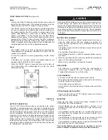
3. Secure the detection wire by completing the following steps:
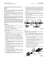
See Figure 25.
a. Start at the beginning of the detection wire leading into the
hazard area. Secure the detection wire every 12 to 18 in.
(30 to 45 cm) using black nylon cable ties, Part No. 56691,
and protective coverings, Part No. 56692, at points of
securement. Secure more often if necessary. Attach the
wire to mounting surfaces, decks, struts, etc., always
keeping System Planning guidelines in mind.
NOTICE
The minimum bend radius for detection
wire must not be less than 2 1/2 in. (64
mm).
Detection wire must never be routed through a hole or
near sharp edges without being properly protected.
Failure to protect the wire from being cut or abraded
could cause it to short, causing a false discharge.
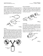
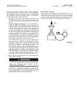
b. Secure the wire at least once immediately before it passes
through a hole in a vertical or horizontal surface. At the
hole, a 1/4 in. (6 mm) rubber sleeve, Part No. 56692, or a
special grommet to fit the hole should be used to protect
the wire from wear due to vibration. If the rubber sleeve
might slide from under the cable tie and off the wire, tape
the rubber sleeve to the wire using electricianʼs tape to
keep it from sliding (see Figure 25). This hose protection
should also be used at locations where the wire would rub
against other hard surfaces, rough edges, or sharp
corners.
FIGURE 25
000872
!
CAUTION
INSTALLATION
PAGE 14
REV. 02 2012-MAY-18
CHECKFIRE MP-N Electric
Detection and Actuation System Manual
LOCK
NUT
GAS
MOTOR
SET
SCREW
ACTUATOR
BODY
CABLE TIE
1/4 IN.
RUBBER SLEEVE
TAPE AT
BOTH ENDS


