background image

- 12 - 

Ű

 5. Operation 

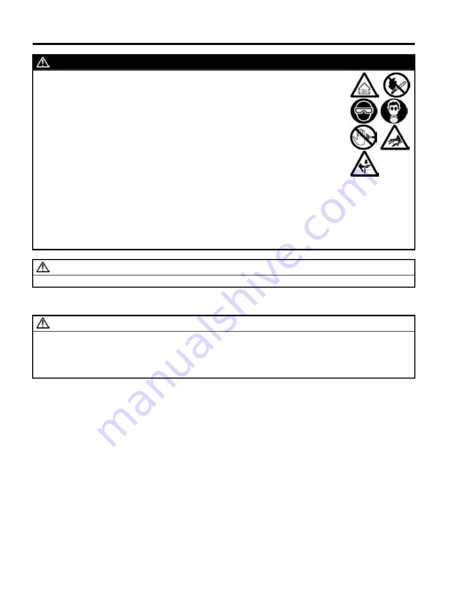
 WARNING

1.  Use in well-ventilated spray booth. 
2.  Avoid any ignition sources such as smoking, open flames or electrical hazard. 
3.  Always wear protective clothing, eyewear, gloves and respirator. 
4.  Never spray toward a person or animals and never pull the trigger of the spray gun 

near the body. 

5.  Never stop or deflect a fluid leak from the spray equipment or fluid hose with your 

hand. Be sure to stop the spray equipment according to 

5-4. Emergency stopping

procedure on page 13. 

6.  Never touch moving parts. 
7.  Always release air and fluid pressure when not the use. 
8.  Always release air and fluid pressure before cleaning, disassembly or service. For 

emergency stop and to prevent unintended operation, a shut off valve is installed on 
this unit to stop the air supply. 

9.  Be sure to use the spray equipment at less than the maximum working pressure. If not, 

it can cause spray equipment failure, malfunction, serious injury or death. 

10.  Never modify this unit for any other applications. 
11.  Never use this unit to spray or supply food products. 
12.  If operation appears incorrect, immediately stop operation and find the cause. See 

8.

Trouble Shooting

 on page 16. 

13.  Never use until the problem has been solved. 

 CAUTION

1.  Be sure to use compatible fluid and cleaning fluid with the wetted parts of this unit. 

5-1. Flushing 

 IMPORTANT 

1.  Flush fluid passages of this unit completely with cleaning fluid before first use and every time after use. If 

not, it can cause finish problem and pump malfunction. 

2.  Always fully close or fully open circulation valve. Opening valve halfway can cause seat wear, fluid leakage 

and lack of fluid pressure. 

3.  Be sure to follow local guidelines for proper cleaning and fluid disposal procedures. 

Refer to 

Fig.1

 on page 8 or 

Fig.2

 on page 9 to find reference letters. 

1.  Remove air cap set and nozzle tip from spray gun. 
2. Close 

Air Regulators

 (C and F) fully. 

3. Open 

Circulation Valve

 (G). 

4. Set 

Emergency Valve

 (D) to “

Operating

” position. 

5. Put 

Suction Hose Set

 (E) and 

Circulation Tube

 (H) into cleaning fluid container. 

6. Adjust 

Air Regulator

 (C) to 22 - 73psi (0.15 - 0.5MPa, 1.5 - 5bar) slowly. 

7.  Circulate cleaning fluid or dump to another container through 

Circulation Tube

 (H). 

8.  Point the spray gun toward to container and pull the trigger of the spray gun. Be sure that compressed air is 

not supplied to the spray gun before pulling the trigger. 

9. Close 

Circulation Valve

 (G). 

10.  Circulate cleaning fluid or dump to another container through the spray gun. 
11.  After flushing, lift 

Suction Hose Set

 (E) from container and keep operating pump until air comes out of spray 

gun.

12. Open 

Circulation Valve

 (G) and release the trigger of spray gun. 

13.  Keep operating until air comes out from 

Circulation Tube

 (H). 

14. Close 

Air Regulators

 (C and F) fully. 

Summary of Contents for MSU-111N

Page 1: ...13 1 Stand Mount MSU 113N 13 1 Cart Mount MSU 114N 13 1 Wall Mount MSU 323N 17 1 Cart Mount MSU 324N 17 1 Wall Mount This instruction manual contains IMPORTANT WARNINGS CAUTIONS and INSTRUCTIONS Read...

Page 2: ...tions of the symbols are as follows Warning and caution WARNING This symbol indicates that a potentially hazardous situation may result in serious injury or death if not followed CAUTION This symbol i...

Page 3: ...n Safety Precautions 1 Safety Warnings 2 2 Specifications 4 3 Functions 8 4 Setup 10 5 Operation 12 6 Cleaning 14 7 Maintenance 15 8 Trouble Shooting 16 9 Disassembly and Assembly 18 10 Parts List 27...

Page 4: ...ly if cracked damaged bent crushed distorted or worn Use of such hoses can cause damage 3 Never bend hoses with a radius of less than 2in 50mm or put heavy items on top of hoses 4 Keep hoses away from...

Page 5: ...iew the Material Safety Data Sheet MSDS from paint or fluid manufacturer IMPORTANT 1 Check to ensure that this unit has not been damaged during transportation 2 Install this unit in a dry clean and we...

Page 6: ...let BSPP1 4 G1 4 Maximum Inlet Air Pressure 98psi 0 68MPa 6 8bar Maximum Fluid Working Pressure 1274psi 8 8MPa 88bar Maximum Fluid Output 0 50gal min 1 9L min Maximum Cycle 110cycles min Maximum Fluid...

Page 7: ...98psi 0 68MPa 6 8bar Maximum Fluid Working Pressure 1666psi 11 5MPa 115bar Maximum Fluid Output 0 93gal min 3 5L min Maximum Cycle 92cycles min Maximum Fluid Output per Cycle 1 30oz cycle 38 3mL cycl...

Page 8: ...izontal axis of the chart 2 Follow vertical to the intersection with the air consumption curve of selected inlet air pressure 3 Follow right to the vertical axis of the chart to read air consumption H...

Page 9: ...CE EX Marking 4 Equipment group II Category Gas2G Area Gas Maximum surface temperature temperature class T6 X marking Any static electricity discharge from the spray gun is to be diverted to the grou...

Page 10: ...7131N stainless steel model B Pop off Valve Working pressure 116psi C Air Regulator For pump operation with locking knob feature D Emergency Valve Emergency air shut off valve E Suction Hose Set with...

Page 11: ...1171CNE stainless steel model B Pop off Valve Working pressure 116psi C Air Regulator For pump operation with locking knob feature D Emergency Valve Emergency air shut off valve E Suction Hose Set wi...

Page 12: ...ions 4 Be sure to follow fire prevention electrical and other local regulations IMPORTANT 1 Install this unit in a dry clean and well ventilated area 2 Use clean air filtered through a dryer and a fil...

Page 13: ...nd F fully 3 Open Circulation Valve G 4 Set Emergency Valve D to Operating position 5 Turn on the air supply to the unit 6 Remove Suction Hose Set E from the pump fluid inlet and adjust Air Regulator...

Page 14: ...d with the wetted parts of this unit 5 1 Flushing IMPORTANT 1 Flush fluid passages of this unit completely with cleaning fluid before first use and every time after use If not it can cause finish prob...

Page 15: ...trigger 9 Close Circulation Valve G 10 Circulate fluid through the spray gun until fluid does not contain bubbles 11 Release the trigger of spray gun 5 3 Spraying IMPORTANT 1 See spray gun instruction...

Page 16: ...every time after use If not it can cause finish problem and pump malfunction 2 Always fully close or fully open the circulation valve Opening the valve halfway can cause seat wear fluid leakage and l...

Page 17: ...ry 300 hours 1 Tighten V packing upper of plunger pump Every 500 hours 1 Put general purpose grease on the moving parts of air motor Every 1 000 hours 1 Overhaul 2 Replace parts with repair service ki...

Page 18: ...re at Air Regulator C Fluid Filter 6 5 7 3 Suction Filter 8 5 or spray gun filter is clogged Clean or replace Suction Hose Set E is clogged Clean or replace V packing upper 2 45 3 46 or lower 2 49 3 5...

Page 19: ...fix Fluid hose or joint is loose or damaged Tighten or replace Paint leaks from fluid hose or joint Paint builds up on seat of fluid joint Clean or replace Wet Cup 2 42 3 40 is loose Tighten 1 Paint...

Page 20: ...PORTANT 1 Do not damage or bend air motor rod changeover rod and rod and be sure to check that these are free of foreign matter It can cause pump malfunction a PP 7131N 13 1 pump 1 Loosen the four bol...

Page 21: ...e air motor body 5 Push the changeover body downward 6 Loosen the nuts and remove 7 Loosen the valve shafts until its surface and the surface of the changeover bar are at the same level 8 Lift the cha...

Page 22: ...packing lower expect during replacement 1 Loosen the suction tube and remove the packing upper 2 Loosen the valve adaptor and remove packing lower 3 Remove the pin and ball 4 Loosen the wet cup 5 Loo...

Page 23: ...he three nuts and remove the spring washers 10 Remove the suction body section from the connecting rods 11 Loosen the wet cup and remove the following parts Sleeve or Slide ring V packing female adapt...

Page 24: ...Make sure that the switch block switches up when the air motor rod is at the end of the up stroke and switches down when the air motor rod is at the end of the down stroke 1 Place the rod guide onto...

Page 25: ...lacing the valve shaft push the changeover bar downward and adjust the clearance between the valve shaft and the piston to 2mm 0 08inch each sides 3 When tightening the nuts on the changeover rod the...

Page 26: ...linder and the head bolt It is easy to pull up the changeover rod during assembly 6 Place the o rings and the air cylinder onto the air motor body and tighten the four bolts 7 Replace the o ring and t...

Page 27: ...parts into the suction body V packing male adaptor V packing set upper V packing female adaptor Sleeve or Slide ring 2 Loosely tighten lightly the wet cup to the suction body 3 Place the suction body...

Page 28: ...ntenance or service run the pump to be sure that the pump operates collect according to 4 3 Checking operation procedure on page 11 12 Tighten the wet cup 13 Clean any grease or lube oil on the V pack...

Page 29: ...14N Wall Mount 1 6 MSU 111N Stand Mount 1 7 MSU 113N Cart Mount No Description Qty No Description Qty 1 1 Plunger pump PP 7131N 1 1 5 Suction hose set 4 1 2 Air regulator set 1 1 6 Stand set 4 1 3 Cir...

Page 30: ...10 1 2 17 1 pump unit 1 1 1 2 1 4 1 5 MSU 324N Wall Mount 1 7 MSU 323N Cart Mount No Description Qty 1 1 Plunger pump PP 1171CNE 1 1 2 Air regulator set 1 1 4 Fluid filter set 1 1 5 Suction hose set...

Page 31: ...29 10 Parts List 10 2 Plunger pump 13 1 PP 7131N...

Page 32: ...packing male adaptor lower 1 2 17 Switch block 1 2 49 V packing lower 4 2 18 Block guide plate 1 2 50 V packing female adaptor lower 1 2 19 Seat block 1 2 51 Ball upper 1 2 20 O ring 2 2 52 Packing up...

Page 33: ...31 10 Parts List 10 3 Plunger pump 17 1 PP 1171CNE...

Page 34: ...2 3 52 Spacer 1 3 18 Air piston 1 3 53 V packing female adaptor lower 1 3 19 Screw 2 3 54 V packing lower 4 3 20 Changeover bar stay 2 3 55 Ball upper 1 3 21 Reinforce plate 2 3 56 Valve holder set 1...

Page 35: ...4 Nipple 1 4 5 Air regulator 1 4 6 Tee joint 2 4 7 Nipple 1 4 8 Air filter regulator 1 4 9 Elbow joint 2 4 10 Pressure gauge 2 4 11 Bolt 2 4 12 Nut 2 10 5 Circulation valve set for 13 1 pump unit No D...

Page 36: ...Swivel joint 1 6 10 Spring pin 1 6 11 Filter adaptor 1 6 12 Elbow joint 1 6 13 Nipple 1 6 14 Elbow joint 1 6 15 2 way ball valve 1 6 16 Hose joint 1 6 17 Locking nut 1 10 7 Fluid filter set TF 8N for...

Page 37: ...08 0 21 8 240 NT2002CMU 0 009 0 23 9 270 NT1503CMU 0 011 0 28 12 360 NT2003CMU 0 011 0 29 15 450 NT2503CMU 0 012 0 31 18 540 NT3003CMU 0 013 0 33 21 630 NT3503CMU 0 014 0 35 16 480 NT2004CMU 0 014 0 3...

Page 38: ...36 Note...

Page 39: ...37 Note...

Page 40: ...Manual Nr T032 00...

Reviews: