background image


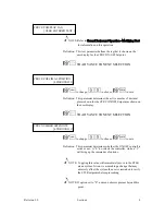
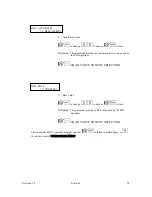
HWC SP1 VALUE 
 

[ Y  UNITS ] 


Y = Setpoint Value 
Units = 

O

F or 

O

C as chosen in setup 


ÿü

 to change, 

õö

 to choose, 

ÿþ

 to save 

 
Definition:  This parameter defines the HWC ON/OFF setpoint value. 


ÿø

 TO ADVANCE TO NEXT SELECTION


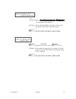
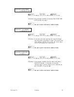
HWC SP1 HYSTERESIS 
 

[ Y  UNITS ] 


Y = Proportional Band Value 
Units = 

O

F or 

O

C as chosen in setup 


ÿü

 to change, 

õö

 to choose, 

ÿþ

 to save 

 
Definition:  This parameter defines the HWC ON/OFF hysteresis 

(deadband) value. 


ÿø

 TO ADVANCE TO NEXT SELECTION 


This completes HWC ON/OFF control program options - 

ÿú

 to return to main display, or 

õ

 to return to start of CONTROLLER SETUP MENU. 


Revision 3.0 

Section 6 

22 


Summary of Contents for AV-9900

Page 1: ...Anderson Instrument Co Inc 156 Auriesville Rd Fultonville NY 12072 Phone 800 833 0081 www anderson negele com Instruction Manual Rev 3 0 Doc 1029 AV 9900 Microprocesor Based HTST Recorder Controller...

Page 2: ......

Page 3: ...r 6 Controller Setup Menu programming Chapter 7 Configuration Menu programming Chapter 8 Test routines Chapter 9 Calibration routines Chapter 10 Model and Revision info Chapter 11 Chart Operation Appe...

Page 4: ...icting access to the Run Program shunt jumper the chart plate seal prevents modifications to circuit boards and input output wiring connections Flow Diversion Valve position is indicated by red and gr...

Page 5: ...ry the resulting output signal based on rising above or falling below the desired Hot Water set point If various products are being processed up to five Hot Water Controllers are available one for eac...

Page 6: ......

Page 7: ...are enclosed in a cardboard box within the container holding the unit Be sure to secure these items before discarding shipping material Select a location for the instrument which is accessible clean w...

Page 8: ...eliminate interference be sure to isolate signal cables from power cables when entering recorder CAUTION To prevent moisture entry or damage to components DO NOT cut case penetrations in sides or top...

Page 9: ...er Supply F1 F2 110 VAC F1 F2 3 amp 220 VAC F1 F2 1 5 amp 7 6 5 4 3 2 L2 TB1 HTST Termination Board Fuses 110 VAC 220 VAC As Per Order Review Instrument Data Tag Prior To Making Field Connections CAUT...

Page 10: ...vary based on the configuration ordered CAUTION Disconnect power to the instrument to prevent electrical shock or component damage 2 5 1 Legal Controls Wiring Wiring to the legal controls FDV Differen...

Page 11: ...less specified at time of order all programming and jumper selections have been pre set at the factory Note The following chart outlines board locations for Input s only Board Location LEFT Input Chan...

Page 12: ...ed cable If wires are removed for installation purposes they must be re wired properly CAUTION Anderson does not recommend splicing of signal cable The possibility will exist for corrosion leading to...

Page 13: ...hould first determine which input you will be working with Cold Product or Hot Water it s type RTD or mA and finally which terminal it wires to The following diagram illustrates the wiring and configu...

Page 14: ...ered or Un powered This can be accomplished by placing a meter DC Volts position across the two sensor leads If a voltage is observed the signal is said to be Powered Wiring can go directly to the mA...

Page 15: ...mitter Power Supply Wiring 2 5 8 mA Retransmission Output Board Wiring Refer to the circuit board locations diagram for assistance in locating the mA retransmission board Retransmission signals are ut...

Page 16: ...and NO terminals for failsafe operation Relay 2 SFLR Alarm 2 High Flow alarm Wire to COM and NO terminals for failsafe operation Relay contacts interface with Legal Flow Control unit found in system...

Page 17: ...This section will detail specifics relating to overall operation of the unit 3 1 Installation of pen cartridge assembly Remove the pen cartridge assembly from its shipping container With mounting tab...

Page 18: ...m parameters can be gained A description of each of the keys is as follows Up Arrow Key Used to move through menus or increase a value Down Arrow Key Used to move through menus or decrease a value Lef...

Page 19: ...ode for completion of the Appendix I Pasteurized Milk Ordinance testing While in sequence mode various parameters scroll over the screen at a timed interval 3 4 1 Display Continuous Mode 1 Operation m...

Page 20: ...the temperature input to the STLR portion of the system A continuous check is made between the two elements Match to 5 O F shift No LED s lit operation allowed 5 O F to 1 O F shift 1 LED lit Forward...

Page 21: ...th the new value being displayed and entered into memory 3 5 2 Changing Text There are two ways to modify text The first Character Modify is accessed by the initial pressing of the key and the second...

Page 22: ...key exits Character Selection and return the unit to Character Modify where selection of another character may be made or again exits Modify While in Character Selection key after modifying a characte...

Page 23: ...tpoint changes etc Changes may be made to display functions as well as selection of the currently active diversion setpoint While in PROGRAM mode full access to all system parameters is allowed NOTE M...

Page 24: ...Revision 3 0 Section 3 8...

Page 25: ...rally used when we have completed a processing run and wish to remove the chart from the AV 9900 The procedure is as follows 1 key to initiate Stop Chart routine 2 Display will show STOP CHART NO YES...

Page 26: ...uence for up to 5 minutes When exiting the Hold sequence the chart printing will be accelerated until the point where real time has again been reached NOTE Chart HOLD may only be initiated while in RU...

Page 27: ...Chart will begin printing at an accelerated speed until all data and events have been transfered from memory to the chart and real time has again been reached 4 2 How Do I Change an STLR Diversion Set...

Page 28: ...the controllers may be placed into Manual mode While in Manual a percentage of output 0 100 may be directly altered by the user This change will immediately influence the resulting controller output...

Page 29: ...for PID mode of operation modulating 4 20 mA output or On Off mode of operation Relay NOTE A menu option exists for selecting whether or not setpoint changes may be made from the RUN mode If set to NO...

Page 30: ...r Setup Menu while in the Program mode If set to YES changes may be made as shown in the upcoming section To toggle this function refer to the appropriate CP HW or SF Controller Setup Menu in section...

Page 31: ...the Factory Prior to making modifications it is recommended that you record current settings 5 1 Function Setup Menu STLR The following section STLR Safety Thermal Limit Recorder will illustrate the...

Page 32: ...hange or to choose to save Definition If STLR Input is being displayed this parameter selects whether both input 1 Primary and input 2 Secondary are displayed or if only input 1 Primary is displayed T...

Page 33: ...and May or may not indicate forward flow condition dependent on presence of SFLR function TO ADVANCE TO NEXT SELECTION STLR SP DISPLAY OPT NOT DISPLAYED IN CONTINUOUS MODE IN SEQUENTIAL MODE IN BOTH M...

Page 34: ...il the following is visible SELECT FUNCTION SETUP With FUNCTION shown in the lower display line key The following will now be visible on the user display SELECT FUNCTION STLR XXXX XXXX NOTE XXXX will...

Page 35: ...CK BLUE GREEN NOT RECORDED to change or to choose to save Definition This parameter determines if the temperature from the Hot Product Probe input is printed to the chart and if so in which color The...

Page 36: ...E O C shown if unit set for Celsius to change to choose to save Definition This parameter allows a correction factor to be added to the STLR Input Values It is used to correct discrepancies between th...

Page 37: ...so in which color The factory default is GREEN TO ADVANCE TO NEXT SELECTION STLR SP DISPLAY OPT NOT DISPLAYED IN CONTINUOUS MODE IN SEQUENTIAL MODE IN BOTH MODES to change to choose to save Definitio...

Page 38: ...or instructions on identifying RUN and PROGRAM mode of operation From the Normal Display key until the following is visible SELECT FUNCTION SETUP With FUNCTION shown in the lower display line key The...

Page 39: ...MODE IN BOTH MODES to change to choose to save Definition This parameter when active will display the output of the CPRC PID Controller A Controller MUST be active The units will be in of output TO A...

Page 40: ...the Normal Display key until the following is visible SELECT FUNCTION SETUP With FUNCTION shown in the lower display line key The following will now be visible on the user display SELECT FUNCTION STLR...

Page 41: ...ure current output selected is not used by another function to change to choose to save Definition This parameter allows the CPRC Input signal to be sent out as a 4 20 mA retransmission signal TO ADVA...

Page 42: ...de to change to choose to save Definition This parameter allows a correction factor to be added to the Cold Product input value It is used to correct discrepancies between the actual cold product valu...

Page 43: ...RC OUT RECORDING RED BLACK BLUE GREEN NOT RECORDED to change or to choose to save Definition This parameter when active will record the resulting output of the CPRC PID Controller Only applies if PID...

Page 44: ...change to choose to save Definition This parameter if active allows the current Setpoint of the PID controller associated with the Cold Product to be displayed TO ADVANCE TO NEXT SELECTION CPRC ALARM...

Page 45: ...ave Definition This parameter allows the user to select an optional alarm for the Cold Product process This alarm may be tied to an event flag LED or relay TO ADVANCE TO NEXT SELECTION CPRC ALARM2 SET...

Page 46: ...ent on activation by another parameter Access is gained as follows Note Refer to General Instrument Operations section for instructions on identifying RUN and PROGRAM mode of operation From the Normal...

Page 47: ...to choose to save Definition This parameter when active displays the output of the controller associated with the Hot Water function TO ADVANCE TO NEXT SELECTION HWC SP DISPLAY OPT NOT DISPLAYED IN CO...

Page 48: ...he Normal Display key until the following is visible SELECT FUNCTION SETUP With FUNCTION shown in the lower display line key The following will now be visible on the user display SELECT FUNCTION STLR...

Page 49: ...sure current output selected is not used by another function to change to choose to save Definition This parameter allows the HWC Input signal to be sent out as a 4 20 mA retransmission signal TO ADV...

Page 50: ...This parameter allows the user to choose the type of control action applied to the HWC control output TO ADVANCE TO NEXT SELECTION HWC CURRENT OUTPUT 1 THROUGH 4 NOTE This parameter only active if PI...

Page 51: ...NTINUOUS MODE IN SEQUENTIAL MODE IN BOTH MODES to change to choose to save Definition This parameter when active will display the resulting output of the HWC PID Controller if controller is active TO...

Page 52: ...YPE NONE OFF LOW SIGNAL VALUE HIGH RATE VALUE to change to choose to save Definition This parameter allows the user to select an optional alarm for the Hot Water Loop This alarm may be tied to an even...

Page 53: ...larm may be tied to an event flag LED or relay TO ADVANCE TO NEXT SELECTION HWC ALARM2 SETPOINT X O F NOTE Will display in O C if unit set for Celcius to change to choose to save Definition This param...

Page 54: ...pendent on activation by another parameter Access is gained as follows Note Refer to General Instrument Operations section for instructions on identifying RUN and PROGRAM mode of operation From the No...

Page 55: ...hoose to save Definition This parameter when active displays the output of the controller associated with the SFLR function TO ADVANCE TO NEXT SELECTION SFLR SP DISPLAY OPT NOT DISPLAYED IN CONTINUOUS...

Page 56: ...mode of operation From the Normal Display key until the following is visible SELECT FUNCTION SETUP With FUNCTION shown in the lower display line key The following will now be visible on the user disp...

Page 57: ...ave Definition This parameter selects NORMAL run mode with a SIMULATED run mode option for demonstration purposes TO ADVANCE TO NEXT SELECTION SFLR INP TRANSMIT TO CURRENT OUTPUT X NOTE X Current outp...

Page 58: ...YED to change to choose to save Definition This parameter when active will display the Flow Rate input value TO ADVANCE TO NEXT SELECTION SFLR INP CORRECTION X units NOTE Units as programmed will be d...

Page 59: ...NCE TO NEXT SELECTION SFLR CURRENT OUTPUT 1 THROUGH 4 NOTE This parameter only active if PID chosen as control type to change to choose to save Definition This parameter will tie a PID control output...

Page 60: ...NTINUOUS MODE IN SEQUENTIAL MODE IN BOTH MODES to change to choose to save Definition This parameter when active will display the resulting output of the SFLR PID Controller if controller is active TO...

Page 61: ...ut This function is NOT utilized on typical Pasteurization loops SFLR ALARM1 TYPE NONE OFF LOW SIGNAL VALUE HIGH RATE VALUE to change to choose to save Definition MUST remain at High Rate Value select...

Page 62: ...ition MUST remain at LOW SIGNAL VALUE selection for proper utilization as High Flow alarm Causes Alarm 2 relay to be failsafe active when above High Flow setpoint Above High Flow setpoint condition wi...

Page 63: ...This completes SFLR program options to return to main display or to return to start of FUNCTION MENU Revision 3 0 Section 5 33...

Page 64: ......

Page 65: ...difications to program parameters on a unit that has been in operation RECORD ALL PARAMETERS before making changes 6 1 Controller Setup Menu STLR 6 1 1 STLR Shunt Position PROGRAM MODE While in the PR...

Page 66: ...ER ENTERED TEXT NOTE Refer to General Instrument Operation Modifying Text for information on this operation Definition This text parameter defines the tag that is shown on the user display for the STL...

Page 67: ...XT SELECTION STLR SPX VALUE Y UNITS X Diversion Setpoint 1 through 5 Y Setpoint Value Units O F or O C as chosen in setup to change to choose to save Definition This parameter is one of the 5 availabl...

Page 68: ...OUGH 5 to change to choose to save Definition This value allows the selection of currently active STLR Diversion Setpoint while in the STLR Control er Program Menu l NOTE The new Diversion Setpoint do...

Page 69: ...given if no Cold Product or Hot Water controllers active key until STLR is flashing then key to select Available parameters are STLR CURRENT SP 1 THROUGH 5 to change to choose to save Definition This...

Page 70: ...RC Control related parameters Access is gained as follows From the Normal Display press the key until the following is visible SELECT CONTROLLER SETUP With FUNCTION shown in the lower display line key...

Page 71: ...O NEXT SELECTION CPRC CONTROL TUNING YES NO to change or to choose to save Definition This parameter determines if CPRC Controller ON OFF tuning parameters are accessible while the unit is in RUN mode...

Page 72: ...own for the CPRC ON OFF Setpoint as shown on the user display TO ADVANCE TO NEXT SELECTION CPRC NUMBER SETPOINTS 0 THROUGH 1 to change to choose to save Definition This parameter determines whether th...

Page 73: ...TO ADVANCE TO NEXT SELECTION CPRC HYSTERESIS Y UNITS Y Proportional Band Value Units O F or O C as chosen in setup to change to choose to save Definition This parameter defines the CPRC ON OFF Hyster...

Page 74: ...display line key The following will now be visible on the user display CONTROL FUNCTION STLR XXXX XXXX NOTE XXXX will be vary depending on which options the unit has key until CPRC is flashing key to...

Page 75: ...oller Output may be forced to a percentage of signal This will ensure a safe condition during the error period Ex Air To Open valve 0 will ensure valve stays closed TO ADVANCE TO NEXT SELECTION CPRC O...

Page 76: ...fines the tag that is shown on the user display for the CPRC PID Control Output TO ADVANCE TO NEXT SELECTION CPRC OUT DECIMAL POS 0 THROUGH 3 to change to choose to save Definition This parameter dete...

Page 77: ...R ERR SFLR OUT SFLR ERR FLOW OUT FLOW ERR CPRC OUT CPRC ERR HWC OUT HWC ERR OP INP 1 OP INP 2 OP INP 3 OP INP 4 OP INP 5 OP INP 6 OP INP 7 OP INP 8 DA1 DA2 DA3 DA4 DA5 DA6 DA7 DA8 F1 F2 F3 F4 F5 RESET...

Page 78: ...ose to save Definition This parameter determines if CPRC Controller PID Setpoint is accessible while the unit is in RUN mode TO ADVANCE TO NEXT SELECTION CPRC SP DISPLAY TAG USER ENTERED TEXT NOTE Ref...

Page 79: ...o save Definition This parameter determines whether the PID controll is active or not A 0 de selects the controller while a 1 will bring up the remainder of options NOTE Toggling this value will immed...

Page 80: ...r defines the CPRC PID controller setpoint value TO ADVANCE TO NEXT SELECTION CPRC PROP BAND Y UNITS Y Proportional Band Value Units O F or O C as chosen in setup to change to choose to save Definitio...

Page 81: ...NCE TO NEXT SELECTION CPRC AUTO RESET Y REPEATS MIN Y Auto Reset Value to change to choose to save Definition This parameter provides an Automatic Reset value used by the PID algorithm TO ADVANCE TO N...

Page 82: ...This completes CPRC Controller program options to return to main display or to return to start of CONTROLLER MENU Revision 3 0 Section 6 18...

Page 83: ...following is visible SELECT CONTROLLER SETUP With FUNCTION shown in the lower display line key The following will now be visible on the user display CONTROL FUNCTION STLR XXXX XXXX NOTE XXXX will be v...

Page 84: ...TO NEXT SELECTION HWC CONTROL TUNING YES NO to change or to choose to save Definition This parameter determines if HWC controller ON OFF tuning parameters are accessible while the unit is in RUN mode...

Page 85: ...ON OFF setpoint as shown on the user display TO ADVANCE TO NEXT SELECTION HWC NUMBER SETPOINTS 0 THROUGH 1 to change to choose to save Definition This parameter determines whether the ON OFF controll...

Page 86: ...XT SELECTION HWC SP1 HYSTERESIS Y UNITS Y Proportional Band Value Units O F or O C as chosen in setup to change to choose to save Definition This parameter defines the HWC ON OFF hysteresis deadband v...

Page 87: ...er display line key The following will now be visible on the user display CONTROL FUNCTION STLR XXXX XXXX NOTE XXXX will be vary depending on which options the unit has key until HWC is flashing key t...

Page 88: ...oller output may be forced to a percentage of signal This will ensure a safe condition during the error period Ex Air To Open valve 0 will ensure valve stays closed TO ADVANCE TO NEXT SELECTION HWC OU...

Page 89: ...efines the tag that is shown on the user display for the HWC PID control output TO ADVANCE TO NEXT SELECTION HWC OUT DECIMAL POS 0 THROUGH 3 to change to choose to save Definition This parameter deter...

Page 90: ...R ERR SFLR OUT SFLR ERR FLOW OUT FLOW ERR CPRC OUT CPRC ERR HWC OUT HWC ERR OP INP 1 OP INP 2 OP INP 3 OP INP 4 OP INP 5 OP INP 6 OP INP 7 OP INP 8 DA1 DA2 DA3 DA4 DA5 DA6 DA7 DA8 F1 F2 F3 F4 F5 RESET...

Page 91: ...ose to save Definition This parameter determines if HWC controller PID setpoint is accessible while the unit is in RUN mode TO ADVANCE TO NEXT SELECTION HWC SP DISPLAY TAG USER ENTERED TEXT NOTE Refer...

Page 92: ...save Definition This parameter determines whether the PID controll is active or not A 0 de selects the controller while a 1 will bring up the remainder of options NOTE Toggling this value will immedi...

Page 93: ...al Band Value Units O F or O C as chosen in setup to change to choose to save Definition This parameter defines the HWC PID controller Proportional Band value TO ADVANCE TO NEXT SELECTION HWC INTEG BA...

Page 94: ...e PID algorithm TO ADVANCE TO NEXT SELECTION HWC RATE Y MINUTES Y Rate Value to change to choose to save Definition This parameter provides a Rate value used by the PID algorithm TO ADVANCE TO NEXT SE...

Page 95: ...Control related parameters Access is gained as follows From the Normal Display press the key until the following is visible SELECT CONTROLLER SETUP With FUNCTION shown in the lower display line key Th...

Page 96: ...O NEXT SELECTION SFLR CONTROL TUNING YES NO to change or to choose to save Definition This parameter determines if SFLR Controller ON OFF tuning parameters are accessible while the unit is in RUN mode...

Page 97: ...wn for the SFLR ON OFF Setpoint as shown on the user display TO ADVANCE TO NEXT SELECTION SFLR NUMBER SETPOINTS 0 THROUGH 1 to change to choose to save Definition This parameter determines whether the...

Page 98: ...ADVANCE TO NEXT SELECTION SFLR HYSTERESIS Y UNITS Y Proportional Band Value Units O F or O C as chosen in setup to change to choose to save Definition This parameter defines the SFLR ON OFF Hysteresi...

Page 99: ...own in the lower display line key The following will now be visible on the user display CONTROL FUNCTION STLR XXXX XXXX NOTE XXXX will be vary depending on which options the unit has key until SFLR is...

Page 100: ...oller Output may be forced to a percentage of signal This will ensure a safe condition during the error period Ex Air To Open valve 0 will ensure valve stays closed TO ADVANCE TO NEXT SELECTION SFLR O...

Page 101: ...fines the tag that is shown on the user display for the SFLR PID Control Output TO ADVANCE TO NEXT SELECTION SFLR OUT DECIMAL POS 0 THROUGH 3 to change to choose to save Definition This parameter dete...

Page 102: ...SFLR ERR FLOW OUT FLOW ERR CPRC OUT CPRC ERR HWC OUT HWC ERR OP INP 1 OP INP 2 OP INP 3 OP INP 4 OP INP 5 OP INP 6 OP INP 7 OP INP 8 DA1 DA2 DA3 DA4 DA5 DA6 DA7 DA8 F1 F2 F3 F4 F5 RESET MOD ENTER to c...

Page 103: ...ose to save Definition This parameter determines if SFLR Controller PID Setpoint is accessible while the unit is in RUN mode TO ADVANCE TO NEXT SELECTION SFLR SP DISPLAY TAG USER ENTERED TEXT NOTE Ref...

Page 104: ...o save Definition This parameter determines whether the PID controll is active or not A 0 de selects the controller while a 1 will bring up the remainder of options NOTE Toggling this value will immed...

Page 105: ...al Band Value Units As chosen in setup to change to choose to save Definition This parameter defines the SFLR PID controller Proportional Band value TO ADVANCE TO NEXT SELECTION SFLR INTEG BAND Y UNIT...

Page 106: ...PID algorithm TO ADVANCE TO NEXT SELECTION SFLR RATE Y MINUTES Y Rate Value to change to choose to save Definition This parameter provides a Rate value used by the PID algorithm TO ADVANCE TO NEXT SE...

Page 107: ...te Refer to General Instrument Operations section for instructions on identifying RUN and PROGRAM mode of operation From the Normal Display key until the following is visible SELECT CONFIGURATION With...

Page 108: ...er allows setting the current date TO ADVANCE TO NEXT SELECTION CURRENT TIME AM PM XX XX XX to change to choose Hour to save to change to choose Minutes to save to change to choose AM PM to save Defin...

Page 109: ...eration From the Normal Display key until the following is visible SELECT CONFIGURATION With CONFIGURATION shown in the lower display line key The following will now be visible on the user display CON...

Page 110: ...g is a user entered string which may be viewed on the display TO ADVANCE TO NEXT SELECTION TEMPERATURE UNITS O X to change to choose to save Definition This parameter selects units of operation O F or...

Page 111: ...o save to change to choose Day to save to change to choose Year to save Definition This parameter allows setting the current date TO ADVANCE TO NEXT SELECTION CURRENT TIME AM PM XX XX XX to change to...

Page 112: ...to save Definition This parameter selects communications bit rate NOTE Not available for use in field applications TO ADVANCE TO NEXT SELECTION COMMS PARITY ODD EVEN NONE to change to choose to save...

Page 113: ...ructions on identifying RUN and PROGRAM mode of operation From the Normal Display key until the following is visible SELECT CONFIGURATION With CONFIGURATION shown in the lower display line key until t...

Page 114: ...ag that is shown on the user display TO ADVANCE TO NEXT SELECTION STLR INP DECIMAL POS X to change to choose to save Definition This parameter selects active decimal places for the STLR user display T...

Page 115: ...tenance Two Point Hot Product Probe Calibration to change value to choose to save to change correction to choose to save Definition This is a correction parameter used for the low end of the primary e...

Page 116: ...choose to save Definition This is a correction parameter used for the low end of the secondary element in the Hot Product probe TO ADVANCE TO NEXT SELECTION STLR INPUT 2 CORR 2 X AT X NOTE This parame...

Page 117: ...o General Instrument Operation Modifying Text for information on this operation Definition This text parameter defines the SFLR Input Tag that is shown on the user display TO ADVANCE TO NEXT SELECTION...

Page 118: ...EXT SELECTION SFLR INP LIMIT LOW X to change to choose to save Definition This parameter selects low limit for the SFLR input This setting is in units as determined in Function Setup Be sure setting e...

Page 119: ...rrection parameter used for the low end of the SFLR input TO ADVANCE TO NEXT SELECTION SFLR INPUT 1 CORR 2 X AT X NOTE This parameter is documented in Instrument Maintenance SFLR Input Calibration to...

Page 120: ...TYPE RTD Ma to change to choose to save Definition This parameter selects the CPRC input type TO ADVANCE TO NEXT SELECTION CPRC INP RTD TYPE PT 100 00385 DIN PT 100 00392 USA PT 100 00392 SAMA NI 100...

Page 121: ...eter selects active decimal places for the CPRC user display TO ADVANCE TO NEXT SELECTION CPRC INP RANGE LOW X NOTE Not shown if input type RTD Definition This parameter selects low input range for th...

Page 122: ...er selects high limit for the CPRC input This is a factory default setting TO ADVANCE TO NEXT SELECTION CPRC INPUT 1 CORR 1 X AT X NOTE This parameter is documented in Instrument Maintenance CPRC Inpu...

Page 123: ...RC input TO ADVANCE TO NEXT SELECTION This completes the CPRC Input setup menus to return to the normal display or to continue to the next input selection INPUT FUNCTION HWC Start of menu options for...

Page 124: ...Operation Modifying Text for information on this operation Definition This text parameter defines the HWC Input Tag that is shown on the user display TO ADVANCE TO NEXT SELECTION HWC INP DECIMAL POS...

Page 125: ...ange for the HWC input Typical setting is 20 00 mA MUST match output of sensor TO ADVANCE TO NEXT SELECTION HWC INP LIMIT LOW X Definition This parameter selects low limit for the HWC input This is a...

Page 126: ...NEXT SELECTION HWC INPUT 1 CORR 2 X AT X NOTE This parameter is documented in Instrument Maintenance HWC Input Calibration to change value to choose to save to change correction to choose to save Def...

Page 127: ...rameters which affect the simulated inputs All parameters may not be accessible as many are dependent on activation by another parameter Access is gained as follows Note Refer to General Instrument Op...

Page 128: ...lable parameters are STLR SIM SELECTION PRIMARY SECONDARY to change to choose to save Definition This parameter selects start of simulated input setup either Primary or Secondary simulation TO ADVANCE...

Page 129: ...Operation Modifying Text for information on this operation Definition This text parameter defines the STLR PRIMARY SIP tag that is shown on the user display TO ADVANCE TO NEXT SELECTION STLR SIP RANG...

Page 130: ...save Definition This parameter selects the period to be used for PRIMARY simulated input TO ADVANCE TO NEXT SELECTION STLR SIS TYPE OFF NO INPUT SINE WAVE SAWTOOTH SQUARE WAVE SPIKES to change to choo...

Page 131: ...oose to save Definition This parameter selects the high range to be used for SECONDARY simulated input TO ADVANCE TO NEXT SELECTION STLR SIS PERIOD X to change to choose to save Definition This parame...

Page 132: ...number of decimal places to be used for SFLR simulated input TO ADVANCE TO NEXT SELECTION SFLR SIP DISPLAY TAG USER ENTERED TEXT NOTE Refer to General Instrument Operation Modifying Text for informati...

Page 133: ...or SFLR simulated input TO ADVANCE TO NEXT SELECTION SFLR SIP PERIOD X to change to choose to save Definition This parameter selects the period to be used for SFLR simulated input TO ADVANCE TO NEXT S...

Page 134: ...OTE Refer to General Instrument Operation Modifying Text for information on this operation Definition This text parameter defines the CPRC tag that is shown on the user display TO ADVANCE TO NEXT SELE...

Page 135: ...nge to choose to save Definition This parameter selects the period to be used for CPRC simulated input TO ADVANCE TO NEXT SELECTION HWC SIP TYPE OFF NO INPUT SINE WAVE SAWTOOTH SQUARE WAVE SPIKES to c...

Page 136: ...to General Instrument Operation Modifying Text for information on this operation Definition This text parameter defines the HWC tag that is shown on the user display TO ADVANCE TO NEXT SELECTION HWC S...

Page 137: ...s the high range to be used for HWC simulated input TO ADVANCE TO NEXT SELECTION HWC SIP PERIOD X to change to choose to save Definition This parameter selects the period to be used for HWC simulated...

Page 138: ...r parameter The available current outputs are STLR INPUT mA retransmission of STLR Input Temperature SFLR INPUT mA retransmission of SFLR Input Signal SFLR OUTPUT mA output from SFLR PID Controller CP...

Page 139: ...ed variable have been programmed the unit will automatically scroll to the next available function will return to the normal display or will continue to advance through the next parameter set Availabl...

Page 140: ...STLR INP RANGE HIGH X to change to choose to save Definition This parameter selects the range high to be used by output signal Typically matches high end of STLR chart range TO ADVANCE TO NEXT SELECT...

Page 141: ...save Definition This parameter selects the decimal place to be used if output signal displayed or recorded TO ADVANCE TO NEXT SELECTION SFLR INP RANGE LOW X to change to choose to save Definition This...

Page 142: ...FLR INP ERROR VALUE X to change to choose to save Definition This parameter selects the resulting output signal upon an error condition TO ADVANCE TO NEXT SELECTION SFLR OUT CO TYPE 0 20 mA 4 20 mA to...

Page 143: ...used by output signal Typically matches low end of SFLR chart range TO ADVANCE TO NEXT SELECTION SFLR INP RANGE HIGH X to change to choose to save Definition This parameter selects the range high to b...

Page 144: ...L POS X to change to choose to save Definition This parameter selects the decimal place to be used if output signal displayed or recorded TO ADVANCE TO NEXT SELECTION CPRC INP RANGE LOW X to change to...

Page 145: ...PRC INP ERROR VALUE X to change to choose to save Definition This parameter selects the resulting output signal upon an error condition TO ADVANCE TO NEXT SELECTION CPRC OUT CO TYPE 0 20 mA 4 20 mA to...

Page 146: ...ve Definition This parameter selects the range low to be used by output signal Typically matches low end of CPRC chart range TO ADVANCE TO NEXT SELECTION CPRC INP RANGE HIGH X to change to choose to s...

Page 147: ...4 20 mA to change to choose to save Definition This parameter selects the type of HWC Input Signal Retransmission TO ADVANCE TO NEXT SELECTION HWC INP DECIMAL POS X to change to choose to save Definit...

Page 148: ...X to change to choose to save Definition This parameter selects the range high to be used by output signal Typically matches high end of HWC chart range TO ADVANCE TO NEXT SELECTION HWC INP ERROR VAL...

Page 149: ...e to save Definition This parameter selects the decimal place to be used if output signal displayed or recorded TO ADVANCE TO NEXT SELECTION HWC OUT RANGE LOW X to change to choose to save Definition...

Page 150: ...ed by output signal Typically matches high end of HWC chart range TO ADVANCE TO NEXT SELECTION HWC INP ERROR VALUE X to change to choose to save Definition This parameter selects the resulting output...

Page 151: ...instrument configuration it may be necessary to disable one of the standard pens prior to activating one of the optional pens Only one function may be performed per color If all pens are in use an exi...

Page 152: ...rammed the unit will automatically scroll to the next available function will return to the normal display or will continue to advance through the next parameter set Available parameters are STLR INP...

Page 153: ...H DIVISION X to change to choose to save Definition This parameter determines the end of chart scale MUST REMAIN AT 100 TO ADVANCE TO NEXT SELECTION STLR INP ZONE LOW VALUE X to change to choose to sa...

Page 154: ...e to choose to save Definition This parameter determines the frequency at which the scale information will be printed to the chart Example Range 120 220 Divisions set to 20 Chart scale 120 140 160 etc...

Page 155: ...ext parameter defines the STLR SP tag that is printed on the chart scale TO ADVANCE TO NEXT SELECTION STLR SP DECIMAL POS X to change to choose to save Definition This parameter selects the decimal pl...

Page 156: ...hoose to save Definition This parameter determines the start of chart scale value This value automatically tracks the STLR Input Event scale TO ADVANCE TO NEXT SELECTION STLR SP ZONE HIGH VALUE X to c...

Page 157: ...EXT SELECTION STLR SP ERROR POSN DIVISIONS X to change to choose to save Definition This parameter determines where the pen will be positioned on an error condition TO ADVANCE TO NEXT SELECTION This c...

Page 158: ...SFLR INP chart scale TO ADVANCE TO NEXT SELECTION SFLR INP ZONE LOW DIVISION X to change to choose to save Definition This parameter determines the start of chart scale MUST REMAIN AT 0 TO ADVANCE TO...

Page 159: ...change to choose to save Definition This parameter determines the end of chart scale value Programmed per customer order in units matching either Flow or actual unit value received at 20 mA output sta...

Page 160: ...ROR POSN DIVISIONS X to change to choose to save Definition This parameter determines where the pen will be positioned on an error condition TO ADVANCE TO NEXT SELECTION This completes SFLR INP pen se...

Page 161: ...se to save Definition This parameter selects the decimal places for the CPRC INP chart scale TO ADVANCE TO NEXT SELECTION CPRC INP ZONE LOW DIVISION X to change to choose to save Definition This param...

Page 162: ...C INP ZONE HIGH VALUE X to change to choose to save Definition This parameter determines the end of chart scale value TO ADVANCE TO NEXT SELECTION CPRC INP INTERVAL X DIVISIONS to change to choose to...

Page 163: ...r set 7 6 Configuration Menu Chart Messages 7 6 1 Chart Messages Shunt Position RUN MODE No programming access is allowed under the RUN mode 7 6 2 Chart Messages Shunt Position PROGRAM MODE Consult fa...

Page 164: ...NOT ALTER SETTINGS FOR DERIVED ACTUATORS 7 10 Configuration Menu LED s 7 10 1 LED s Shunt Position RUN MODE No programming access is allowed under the RUN mode 7 10 2 LED s Shunt Position PROGRAM MODE...

Page 165: ...LR ALARM 1 SFLR ALARM 2 CPR ALARM 1 CPR ALARM 2 HWC ALARM 1 HWC ALARM 2 CHART RUN STATE DATA COLLECT STATE CONTROL ON STATE FWD FLOW ENABLED FWD FLOW REQUESTED STLR INPUT MISMATCH STLR OUT STLR ERR SF...

Page 166: ...gramming access is allowed under the RUN mode 7 11 2 Relays Shunt Position PROGRAM MODE Note Refer to General Instrument Operations section for instructions on identifying RUN and PROGRAM mode of oper...

Page 167: ...CPR ALARM 1 CPR ALARM 2 HWC ALARM 1 HWC ALARM 2 CHART RUN STATE DATA COLLECT STATE CONTROL ON STATE FWD FLOW ENABLED FWD FLOW REQUESTED STLR INPUT MISMATCH STLR OUT STLR ERR SFLR OUT SFLR ERR CPRC OU...

Page 168: ...elay 1 programmed to SFLR Alarm 1 Relay 2 programmed to SFLR Alarm 2 DO NOT MODIFY this setting Wiring for Legal Flow Meter Based Timing system is connected to normally open contacts of both relays Th...

Page 169: ...Instrument Operations section for instructions on identifying RUN and PROGRAM mode of operation From the Normal Display key until the following is visible SELECT TESTS With TESTS shown in the lower d...

Page 170: ...CAL ED INPUT VALUES FACTORY USE ONLY mA OUTPUTS Verify mA output is functional Follow individual system prompts to initiate and complete desired test Revision 3 0 Section 8 2...

Page 171: ...llows Note Refer to General Instrument Operations section for instructions on identifying RUN and PROGRAM mode of operation From the Normal Display key until the following is visible SELECT CALIBRATIO...

Page 172: ......

Page 173: ...evision Shunt Position RUN MODE PROGRAM MODE From the Normal Display key until the following is visible SELECT MODEL AND REVISION With MODEL AND REVISION shown in the lower display line key to view Mo...

Page 174: ......

Page 175: ...tion Definition This parameter is used as an identification tag It appears on the outside edge of the chart TO ADVANCE TO NEXT SELECTION CHART SPEED 6 HOURS 8 HOURS 12 HOURS 24 HOURS NOTE The U S Past...

Page 176: ...or per hour TO ADVANCE TO NEXT SELECTION MINOR TIME PERIODS XX NOTE If unit has been programmed at the Factory for a Pasteurized Milk Ordinance regulated product this parameter MUST remain at 4 Three...

Page 177: ...line with the exception that NO scale information is printed to the chart TO ADVANCE TO NEXT SELECTION MAJOR LINE PEN COLOR MATCH SCALE COLOR SELECT A COLOR to change or to choose to save Definition T...

Page 178: ...O NEXT SELECTION MINOR LINE PEN COLOR MATCH SCALE COLOR SELECT A COLOR to change or to choose to save Definition This parameter allows selection of the color for the Minor Time line printed to the cha...

Page 179: ...ION TIME PEN COLOR BLUE GREEN RED BLACK to change or to choose to save Definition This parameter allows selection of the color for the Time printed to the chart TO ADVANCE TO NEXT SELECTION evision 3...

Page 180: ...GE LIST PRINT SCALES NOTE If unit has been programmed at the Factory for a Pasteurized Milk Ordinance regulated product this parameter MUST remain at NONE JUST CONTINUE to change or to choose to save...

Page 181: ...ust be installed and maintained in accordance with Anderson instructions Users are responsible for the suitability of the products to their application There is no warranty against damage resulting fr...

Reviews: