BL BK BN
G R W
Primary RTD:
G = Green (Return)
R = Red (Common)
W = White (Common)
Secondary RTD:
BL = Blue (Return)
BK = Black (Common)
BN = Brown (Common)
Removable
Plugs
Seal-Tight
Grommet
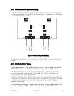
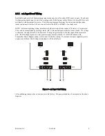
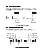
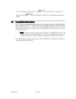
Figure 7 - Hot Product Probe Wiring
2.5.5.
RTD Input Board Wiring
Each half (right or left) of the remaining input cards may be set for either RTD or mA inputs. You should
first determine which input you will be working with (Cold Product or Hot Water), it’s type (RTD or mA),
and finally which terminal it wires to. The following diagram illustrates the wiring and configuration
jumper positions for both an RTD wired to the LEFT or RIGHT of an input card.
G
reen
G
reen
Re
d
Re
d
Whi
te
Whi
te
TB1
JU15
JU16
JU2
JU5
JU
3
JU6
JU7
JU8
TB2
Figure 8 - RTD Input Card Wiring
All conditioning jumpers have been pre-set at the factory. Proper positions have been noted on the above
diagram.
Revision 3.0
Section 2
7


