Evaluation Board User Guide
UG-169
Rev. 0 | Page 9 of 12
Feedback (N) Divider Window
0
91
71
-0
15
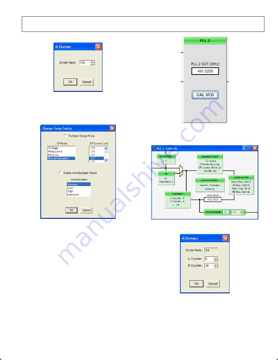
Figure 14. N Divider Window
The feedback divider window shown in Figure 4 is accessed by
clicking the
N DIVI
llows you to set
DER
box in Figure 12. It a
the feedback divider.
Charge Pump Window
0
91
71
-0
16
Figure 15. Charge Pump Window
The
Charge Pump Setup
window shown in Figure 15 is
accessed by clickin
he
PLL 2
box from the main window (see Figure 16)
w configuration of PLL2 (see Figure 17).
g the
CHARGE PUMP
box i
This window is most often used to vary the charge pump
current.
PLL 2 CONTROLS
Clicking t
opens a window to allo
0
91
71
-0
17
Figure 16. PLL2 Box (in Main Window)
Clicking each individual box in the
PLL 2 Controls
window
opens a new window to allow configuration of that block.
0
91
71-
01
8
Figure 17. PLL 2 Controls Window
Feedback (N) Divider Window
0
91
71
-0
19
Figure 18. N Divider Window
The
N Divider
window shown in Figure 18 is accessed by
clicking the
N DIVIDER
box in Figure 17. It allows you to set
the feedback divider.


