Evaluation Board User Guide
UG-169
Rev. 0 | Page 11 of 12
3.
Reconnect the 6 V power supply. This automatically loads
the EEPROM settings into the AD9523. The programmed
settings can be observed at the outputs. In addition, a
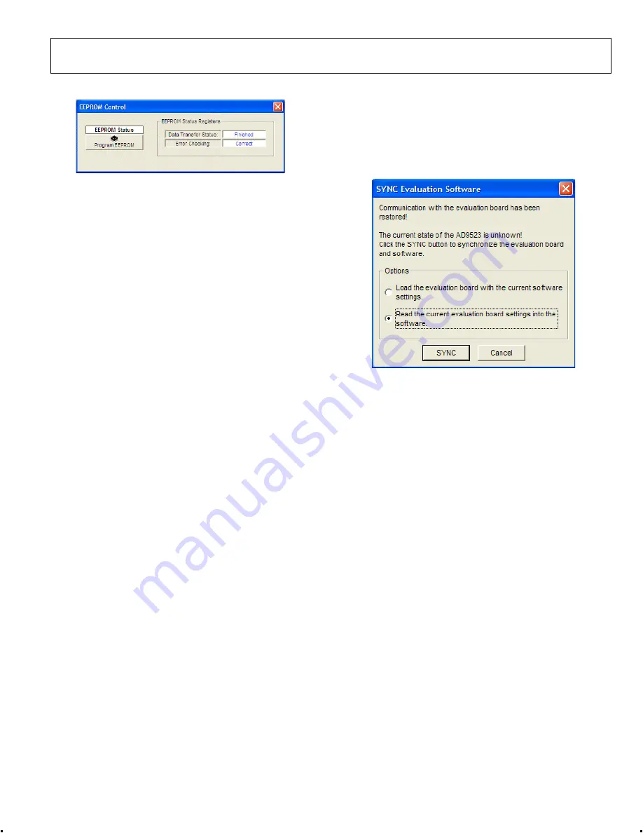
window opens (see Figure 26). Click the second option to
read from the AD9523. This loads the control software
with the current register settings that were programmed by
the EEPROM.
EEPROM CONTROL
0
91
71
-0
23
Figure 25. EEPROM Control Window
0
91
71
-0
24
The
EEPROM Control
window is shown in Figure 25 is
accessed by clicking the
EEPROM
button near the lower left
corner of the main window.
To store the current register settings of the AD9523 to the
EEPROM, click the
Program EEPROM
button. Visually
confirm the
EEPROM Status Registers
section on the right
side of the window to verify that the operation is successful.
To load the values stored in the EEPROM:
1.
Disconnect the 6 V power connector to power down the
AD9523.
2.
Ensure that the EEPROM pin is pulled high by placing the
P4 EEPROM_SEL jumper of the evaluation board across
the center and left (high) pin (see Figure 3).
Figure 26. Software Evaluation Board Software Sync Window


