


Product Information
2
ViewStat Communicating Thermostat
System Components
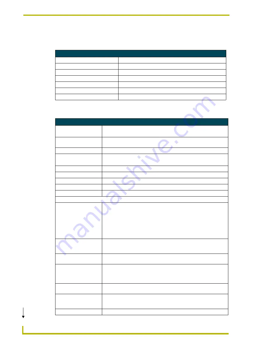
The components in a complete ViewStat system (including optional accessories) are listed below:
ViewStat Specifications
System Components
Component Name
Description
ViewStat (VST)
Communicating thermostat
VST-TTM
Temperature support module (optional)
VST-TRH
Temperature/Humidity support module (optional)
VST-TSF Flush-mount remote sensor
Indoor flush-mount temperature/relative humidity sensor (optional)
VST-TSO Duct/Outdoor remote sensor Duct/Outdoor-mount temperature/relative humidity sensor (optional)
VST-DIST
Distribution Panel
ViewStat Specifications
Control Ports
• HVAC control
• ICSNet
Control Voltage
24 VAC ±20% or 24 VDC ±20% (delivered by an HVAC system or by an external
power supply)
Switched Voltage
18 – 30 VAC
Maximum Operating Current • 2 amps total at rated voltage, through all outputs.
• 1 amps through any one output.
Maximum Surge Current
2.0 A
Control Accuracy
±1.0° F (± 0.56° C)
Control Range
40° – 90° F (4.44° – 32.22° C)
Operating Range
32° – 99° F (0° – 37.22° C)
Baud Rate
9600
Front Panel Components:
Message display
Two types of messages are displayed,
Permanent
and
Temporary
Messages.
• Permanent Messages are those that scroll continually during thermostat
operation.
• Temporary (flashing) Messages are intended to catch your eye and must be
reset to be removed from the display.
Thermostats are shipped with default (permanent) status messages (i.e. mode
status, fan status, equipment status).
Scroll/Set-up buttons
The Scroll/Set-Up buttons function with the set-up features of the thermostat
(see the
Set Up and Configuration
section on page 45). These buttons are
located beneath the faceplate.
Main LCD display
The MAIN DISPLAY (see FIG. 16 on page 25) provides the mode status, tem-
perature and system status information.
Mode button
Five modes of operation are available: OFF, COOL, HEAT, AUTO, and EM.
HEAT (for heat pumps only). The mode of operation indicates how you want
your heating and cooling equipment to operate. This button is located beneath
the faceplate.
Fan button
The fan can be operated continuously (FAN ON) or only when there is a need to
heat or cool. This button is located beneath the faceplate.
Enter button
The Enter (or Network Override) button is used to override the home automation
system, to clear temporary flashing messages on the message display and with
the set-up features of the thermostat.
Adjust buttons
The Adjust buttons adjust the heating and cooling temperature settings.
(Cont.)
Summary of Contents for ViewStat
Page 1: ...instruction manual HVAC Controls ViewStat Communicating Thermostat...
Page 6: ...iv ViewStat Communicating Thermostat Table of Contents...
Page 12: ...Product Information 6 ViewStat Communicating Thermostat...
Page 42: ...ViewStat Installation and Wiring 36 ViewStat Communicating Thermostat...
Page 50: ...Support Module Installation and Wiring 44 ViewStat Communicating Thermostat...
Page 74: ...Operating the Thermostat 68 ViewStat Communicating Thermostat...
Page 75: ...Operating the Thermostat 69 ViewStat Communicating Thermostat...


