background image

Wiring and Installation

7

PRO-DP16 Decor 16-Button PROlink Wall Panel

Wiring and Installation

Preparing the PRO-DP16 and Dimmer Control Cards

Assigning Pack numbers on the dimmer control cards

Each dimmer card in the system must have its own unique PROlink device number, or Pack 

number. The Pack number is assigned via the PROLink DIP switch (SW2) on the dimmer control 

cards:

1.

Turn Off the breaker on the dimmer control card.

2.

Set the Pack number assignment on the individual dimmer control card via the PROlink 

Address DIP switch (SW2).

The Pack number is determined by the value of all the switch position settings. The Pack 

number assignment range is 1-10. The lighting system will not work if you assign Pack 

numbers outside of this range.

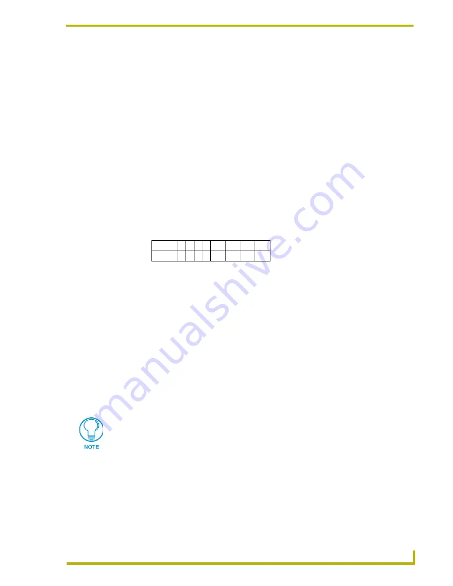
The following table shows the PROlink DIP switch positions and their values:

Set the first enclosure to a Pack value 1 by switching the PROlink DIP switch 1 to On and the 

second enclosure to either a Pack value of 2 (by switching DIP switch 2 to On), or a Pack value 

of 3 (by switching the DIP switches 1 and 2 to On) for a two-enclosure system.

3.

Turn the PRO-DP16 face down and verify that all DIP switches are in the Off position (factory 

default).

4.

Connect a 4-pin PROlink cable to the PROlink bus connector to the rear panel of the 

PRO-DP16.

5.

Power On the dimmer control card.

6.

Press the 

Reset

 button on the dimmer control card.

7.

Verify the PRO-DP16 is communicating with the dimmer control card by watching the 

sequential lighting of each LED on the front panel of the PRO-DP16, and the one-blink action 

of the PROlink LED (rear panel).

Assigning Pack numbers (1-6) on the PRO-DP16 panel

Once each dimmer Pack has a unique device number, you must assign the Packs to the desired 

pushbuttons on the PRO-DP16 panel:

1.

Note the Pack value assigned on the dimmer control card (see previous steps).

2.

Simultaneously press the Up and Down buttons (pushbuttons 14 and 15) until the PGM LED 

lights.

Position 1 2 3 4

5

6

7

8

Value

1 2 4 8 N/A N/A N/A Test

DIP switch #8 is a test switch. It will turn all the lights to full in the On position. It must 
be in the Off position for normal operation.

Summary of Contents for PRO-DP16 DECOR PROLINK FLUSH MOUNT KEYPAD PANEL

Page 1: ...instruction manual Lighting Control PRO DP16 Decor 16 Button Wall Panel...

Page 2: ...RMA is cancelled will be refused AMX is not responsible for products returned without a valid RMA number AMX Corporation is not liable for any damages caused by its products or for the failure of its...

Page 3: ...g the PRO DP16 8 PROlink wiring guidelines 8 Preparing captive wires 8 Using a PROlink 4 pin connector for data and power 8 Using a PROlink 4 pin connector with an external 12 VDC power supply 9 PROli...

Page 4: ...Presets 20 Setting and changing fade times 21 Clearing undefining Presets 21 Pack Select Mode 21 Selecting a Pack 21 Selecting a channel 21 Setting levels 22 Raising and lowering levels 22 Curve Sele...

Page 5: ...s done via rear panel DIP switch settings Specifications Specifications Dimensions HWD 4 68 x 4 75 x 1 72 11 87 cm x 12 05 cm x 4 36 cm Voltage 12 VDC 85 mA maximum per panel Weight 3 78 oz 107 16 g C...

Page 6: ...uttons via the DIP switch on the rear of the panel For details refer to the Using Switch 7 to Enable Either Preset Recall mode or Up Down Ramping section on page 17 11 Clear Clears a preset lighting l...

Page 7: ...le panels that share all or some of the same presets can be used to perform identical functions on a particular pack For installations with multiple panels controlling multiple Packs there can t be an...

Page 8: ...connected to the PRO DP16 via PROlink cable The PROlink cable provides power to the PRO DP16 panel and communication between the panel and pack s For information on setting pack number assignments on...

Page 9: ...a Dimmer Packs to control lighting zones FIG 2 shows an equipment configuration model using the PRO DP16 with a PROlink connection to two dimmer packs FIG 2 Sample product application Controlled light...

Page 10: ...Product Information 6 PRO DP16 Decor 16 Button PROlink Wall Panel...

Page 11: ...by switching DIP switch 2 to On or a Pack value of 3 by switching the DIP switches 1 and 2 to On for a two enclosure system 3 Turn the PRO DP16 face down and verify that all DIP switches are in the Of...

Page 12: ...more than three PRO DPs to a Pack without a separate power supply for the panels see the Using a PROlink 4 pin connector with an external 12 VDC power supply section on page 9 for details Preparing c...

Page 13: ...the Troubleshooting section on page 12 Using a PROlink 4 pin connector with an external 12 VDC power supply Use a 12 VDC power supply when the distance between the Pack and PRO DP16 exceeds 1 000 feet...

Page 14: ...PROlink communications are working properly Full on indicates that the panel is not communicating with the PROlink bus Check the PROlink wiring to the Pack and to any other panels Refer to the Troubl...

Page 15: ...utout dimensions for the PRO DP16 AMX recommends mounting the PRO DP16 in a standard two gang wallbox 1 Use the cutout dimension shown in FIG 5 to cutout the install surface for the PRO DP16 2 Confirm...

Page 16: ...eck phasing Panel LED stays on Check the PROlink wiring Pack number and dimmer Pack settings Cannot select zones 1 6 Check Pack number and mode settings No operation Check PROlink wiring power connect...

Page 17: ...d to two 120 VAC single phase 20A breakers FIG 6 Sample equipment wiring diagram using two Radia Lighting Dimmers RDD DM4 pack 1 RDD DM4 pack 2 1 2 3 4 5 6 CHANNEL PGM PCK CRV LE Neutral PRO DP16 Neut...

Page 18: ...Wiring and Installation 14 PRO DP16 Decor 16 Button PROlink Wall Panel...

Page 19: ...ct the PROlink cable from the PRO DP16 to remove power before changing DIP switch settings Once the switche s are set reconnect the PROlink cable to the PRO DP16 to provide power to the panel On power...

Page 20: ...lt 4 On Off Off Pushbuttons 5 20 8 Off On Off Pushbuttons 9 24 12 On On Off Pushbuttons 13 28 16 Off Off On Pushbuttons 17 32 32 On Off On Pushbuttons 33 48 48 Off On On Pushbuttons 49 64 64 On On On...

Page 21: ...ing scenes and store them as programmed Presets Set switch 8 to Off factory default setting to enable programming of preset levels fade times ramp rates dimmer curves and low end settings When preset...

Page 22: ...DIP Switch Configuration 18 PRO DP16 Decor 16 Button PROlink Wall Panel...

Page 23: ...evels defined as part of the programmed preset You can program a preset for Channel 1 to set a specific light level i e 50 and once saved the Channel 1 preset button will always set Channel 1 to 50 As...

Page 24: ...Mode is active If DIP switch 7 and 8 are On the programming feature is disabled and the panel buttons can only be used to recall Presets Push buttons 1 16 The corresponding recall Preset is based on...

Page 25: ...eset button that you want to clear the recorded presets 3 Press Clear pushbutton 11 to return the selected Preset to an undefined state To clear all channels of their recorded presets 1 Enter Program...

Page 26: ...to set dimmer curves To enter Curve Select mode 1 Enter Program mode indicated by the PGM LED 2 Press Mode pushbutton 16 twice 3 Curve Select mode is indicated by the CRV LED Setting a dimmer curve T...

Page 27: ...ter Low End mode indicated by the LE LED 5 Use the pushbuttons to enter a number between 0 and 99 to specify the low end setting for the selected channel in percentage points For example press pushbut...

Page 28: ...e Off Preset For more information on Preset Recall and Default modes for the panel refer to the DIP Switch Configuration section on page 15 Ramping Presets Ramping a Preset involves either raising or...

Page 29: ...Panel Programming Operation 25 PRO DP16 Decor 16 Button Wall Panel...

Page 30: ...A AUSTRALIA BELGIUM BRAZIL CANADA CHINA ENGLAND FRANCE GERMANY GREECE HONG KONG INDIA INDONESIA ITALY JAPAN LEBANON MALAYSIA MEXICO NETHERLANDS NEW ZEALAND PHILIPPINES PORTUGAL RUSSIA SINGAPORE SPAIN...

Reviews: