Installation
12
4" Color Touch Panels with Audio
6.
Disconnect the power connector from the PSN6.5 or Central Controller until the installation is
complete.
7.
Insert the #6 drywall screws and clips into the two notch locations along the side edges of the
Wall Mount housing as shown in both FIG. 7 on page 11 and in FIG. 8 on page 11.
8.
Carefully insert the main unit (with expansion clips) into the cutout until the rim of the AXD
unit lies flush with the wall and the unit is firmly positioned.
9.
Use a grounded Phillips screwdriver to tighten the #6 drywall screws in a clockwise direction
(FIG. 7 on page 11).
10.
Fasten the main AXD unit to the surface using the two (2) drywall clip sets (consisting of
screws and clips) supplied with the enclosure until the housing is securely fastened and flush
against the wall (FIG. 9).
As the screw is tightened, the clip bends toward the insertion hole and into the wall. This
bending creates a "grip" on the wall by either pressing onto the wall or by securing the drywall
between the housing and the drywall clip.
11.
Carefully remove any of the blank pre-installed plastic pushbuttons by pushing the top rim of
the button towards the LCD panel and applying a small amount of force.
12.
Carefully insert the six (6) desired replacement pushbuttons (up to 12 other pre-labeled buttons
come in the accessory button kit) by grabbing the button at either sides, inserting the
attachment pegs into their respective connector holes, and pressing down firmly (FIG. 10 on
page 13).
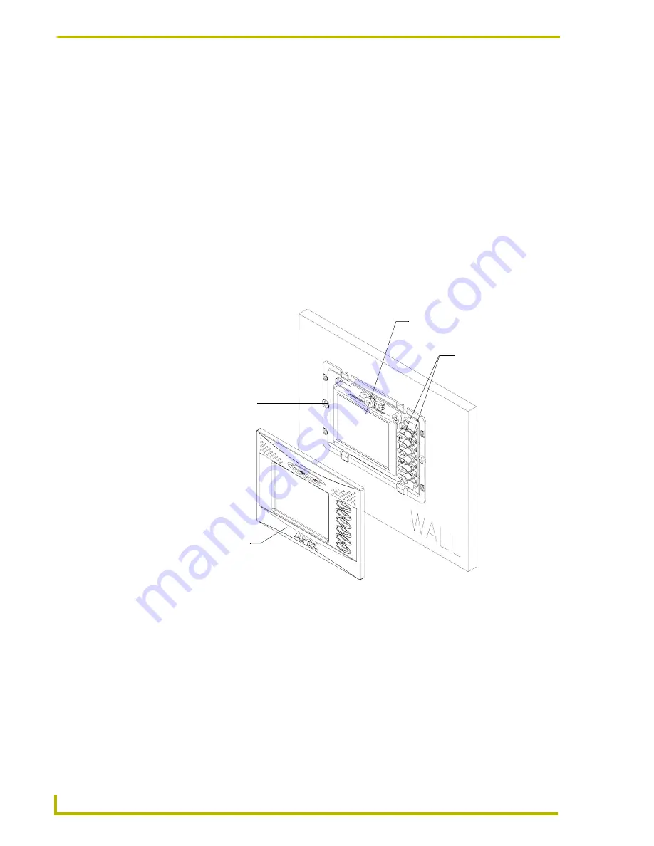
FIG. 9
Screw and clip locations for plasterboard (dry wall) mounting of main AXD unit
Dry wall clips and 2- #6 screws
are inserted through the
notches cut out in the wall
A -
Faceplate
(bezel)
B -
Main
AXD unit
Interchangeable
plastic pushbuttons


