Installation
8
4" Color Touch Panels with Audio
2.
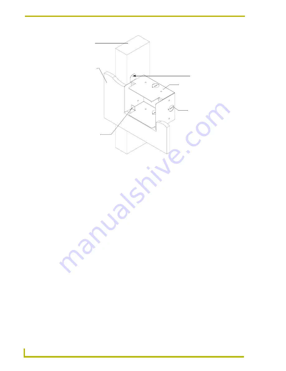
Remove any necessary wiring knockouts from the pre-installed (optional) conduit box
(
C
in FIG. 4 on page 8) where the necessary cables are threaded through for connection to the
touch panel and external devices. The snaps located along the side of the conduit/wallbox can
be snapped off or used to mount the unit to a hard surface (like a wooden beam).
3.
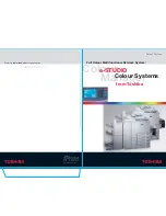
Carefully remove the attached AMX faceplate/bezel (
A
in FIG. 5) from the main AXD unit
(
B
in FIG. 5) by gripping the faceplate from the notches (located along the underside of the
plate) and pulling with gentle force.
4.
Thread the incoming 4-pin mini-AXlink and 8-pin mini-Audio wiring through the cutout
opening in the wall.
5.
Test the wiring by connecting the 4-pin mini-Phoenix connector from the rear AXlink
connector to a PSN6.5 power supply or Central Controller. Verify that the panel is receiving
power and functioning properly to prevent repetition of the installation.
6.
Connect both the AXlink and Audio connectors to the rear of the touch panel. Refer to the
Wiring the Touch Panel
section on page 21 for more detailed wiring instructions.
7.
Disconnect the power connector from the PSN6.5 or Central Controller until the installation is
complete.
FIG. 4
Screw location for attachment on a sample conduit box for a drywall installation
Surface
Stud
CB-CP4/A Conduit Wallbox
Stud fastening holes
Do not use these tabs
to mount a Conduit/
Wallbox
Knockouts
AXD-CP4/A touch
panel housing secure
locations using four
#4-40 screws


