I n s t r u c t i o n M a n u a l
A u t o P a t c h C o n t r o l P a n e l
CP-10
Control Panel
R e l e a s e : 1 / 2 0 / 2 0 0 9
Page 1: ...Instruction Manual AutoPatch Control Panel CP 10 Control Panel Release 1 20 2009 ...
Page 2: ...view 7 Executing Local Presets 8 Defining Global Presets 9 Executing Global Presets 10 Checking the Software Version 11 Installing a CP 10 Remote Control Panel 12 General Specifications 12 Connecting to AMX AutoPatch Matrix Switcher 13 Applying Power 14 Rack Installation 15 Executing a Test Switch 15 Appendix A System Error Codes 17 Common System Error Codes 17 Troubleshooting 18 Technical Support...
Page 3: ...Contents ii CP 10 Instruction Manual ...
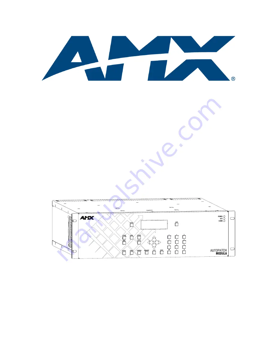
Page 4: ...tima an Optima SD or a Precis SD Overview The CP 10 is used for controlling the system s switches and system attributes Although control panels are optional we recommend one per system for system verification redundant control and troubleshooting FIG 1 illustrates a Modula Distribution Matrix with a CP 10 Control Panel Other models may vary slightly in appearance Note AMX AutoPatch software can al...
Page 5: ...repares the system to receive an input source identification number as the next entry Output destination Key prepares the system to receive an output destination identification number as the next entry Arrow Keys scroll left or right through long lists of outputs required only when an arrow graphic is displayed on the LCD Command screen Preset Key implements local and global presets Program Key di...
Page 6: ...el Key and a level number When executing a switch on a level other than the default e g video alone is usually VM 1 you must press the Level Key and the desired level number When specifying a level be sure it includes all the signals you want to route Executing Switches In an execute switch command either an input or an output can be selected first You can enter multiple output signals but only on...
Page 7: ... and enter 2 5 Press the Take Key Input 1 is routed to Output 2 and the system returns to the Command screen To execute a switch with multiple outputs 1 Complete Steps 1 through 3 above 2 Press an Output Key and then press the Space Key repeating until all desired outputs are selected use no more than 33 outputs at one time If necessary use the left and right arrow keys to navigate through the ent...
Page 8: ...utputs currently receiving the input s signal Once in Status mode the CP 10 stays in Status mode until the Cancel Key is pressed You can return to the Command screen at any time by pressing the Cancel Key The following example verifies the signal status for Input 2 on Level 0 To verify the status of an input signal 1 At the Command screen press the Status Key The Status screen appears 2 Press the ...
Page 9: ...atus of Output 9 on Level 0 To verify the status of an output signal 1 At the Command screen press the Status Key The Status screen appears 2 Press the Level Key and enter 0 3 Press the Output Key and enter 9 4 Press the Take Key An input The status screen below left indicates that Output 9 is receiving a signal from Input 3 No inputs The Status screen below right displays DIS disconnect in the In...
Page 10: ...nt signal routings regardless of the number of levels involved and any digital gain and or volume settings Before defining a Global Preset route the system to the desired state including audio settings if applicable A global preset number is assigned to a system state during runtime using the CP 10 Control Panel or BCS commands and is stored in the switcher s non volatile memory That system state ...
Page 11: ...xecute a local preset 1 At the Command screen press the Preset Key The Global preset screen appears 2 Press the Level Key to access the Local Preset screen The Local preset screen appears with the cursor after the Level prompt 3 Enter 0 for the level Caution Before selecting multiple presets make sure all the presets switch on the same level 4 Press the Preset Key again and enter 6 When entering m...
Page 12: ...ogram prompt appears with the cursor after the prompt Note From the Global Preset screen press the Preset key to toggle between the Program prompt and the Execute prompt 4 Enter 3 as the number to be associated with the current system state 5 Press the Take Key The current system state can now be recalled at any time by executing Global Preset 3 The system returns to the Command screen Note We str...
Page 13: ...Key Note When you execute a global preset the system routes the switches immediately To execute a global preset 1 At the Command screen press the Preset Key The Global Preset screen appears with the cursor after the Execute prompt 2 Enter 3 3 Press the Take Key Global Preset 3 is executed and the system returns to the Command screen ...
Page 14: ...the Software Version Use the following steps to check the software version of the CP 10 Control Panel To check the software version 1 Press the Cancel Key 2 At the Command screen press the Program Key The Software Version screen appears Current software version number ...
Page 15: ...cifications Rear View Parameter Value Cable for XNNet Communications Two conductor 20 AWG 7 28 strand cable with a drain wire or shield such as Alpha 2412C customer supplied Maximum length of cable 1000 ft 305 m total including linked panels Power 7 VDC to 12 VDC 500 mA Operational Temperature 32 F to 110 F 0 C to 43 C Humidity 0 to 90 non condensing Dimensions 1 0 in 2 54 cm depth 18 9 in 48 0 cm...
Page 16: ... On the rear of the panel plug the AMX AutoPatch pigtail into the Comm Link connector FIG 5 3 On the matrix switcher s CPU unplug the REMOTE XNNet connector for REMOTE connector location see the matrix switcher documentation 4 Loosen the two outer screws on the connector 5 Insert the two wires from the CP 10 Remote into the two outer slots of the REMOTE connector on the matrix switcher leaving the...
Page 17: ...MX AutoPatch transformer the side of the wire with the white stripe is positive and the other side is ground To apply power to the CP 10 Remote using the wall transformer 1 Unplug the CP 10 Remote s power connector 2 Loosen the ground and positive screws 3 Insert the power cable ground and positive wires into the slots FIG 7 and tighten the screws 4 Plug the power connector back into the CP 10 Rem...
Page 18: ...ly power to the panel 4 Wait briefly for the system to establish communication with the remote panel Execute a test switch to make sure the system is working properly see below If the system is not working properly check all system connections and retry the test switch before contacting technical support for contact information see page 18 Executing a Test Switch We recommend completing the instal...
Page 19: ... Press the Input Key and enter 1 4 Press the Output Key and enter 2 5 Press the Take Key Input 1 is routed to Output 2 and the system returns to the Command screen If the system is not working properly check all system connections and retry the test switch before contacting technical support see page 18 ...
Page 20: ...f the enclosures in a multi enclosure system did not acknowledge a control operation command Resend the command Check the Status LED on the rear of each enclosure If any are red contact technical support Check the power indicators Check the link connections between enclosures EFF8002 Enclosure timeout error The operation was not completed before the timer expired Resend the command Check the power...
Page 21: ...e g entering a decibel value in an adjust volume command that is outside the volume range for the audio board Technical Support Before contacting technical support with a question please consult this manual If you still have questions contact your AMX representative or technical support Have your system s serial number ready The system s serial number is normally located on the rear of the enclosu...
Page 22: ...registered trademarks of AMX AMX reserves the right to alter specifications without notice at any time It s Your World Take Control 3000 RESEARCH DRIVE RICHARDSON TX 75082 USA 800 222 0193 469 624 8000 469 624 7153 fax 800 932 6993 technical support www amx com ...