52
Ribbon Guide Assembly Replacement
TOOLS: Philips Screwdriver, six inch long .002” (qty-1), and .004” (qty-2) Feeler Gauges
REMOVAL
Step 1. Remove the printer top cover, 7-pan head screws.
Step 2. Remove ribbon cassette.
Step 3. Remove the carrier cover, 1-pan head screw.
Step 4. Disassemble the print head by removing 2-pan head screws (S-6) from the head carrier
and pull the printhead toward the front of the printer. Place the print head on top of the
unit, out of the way.
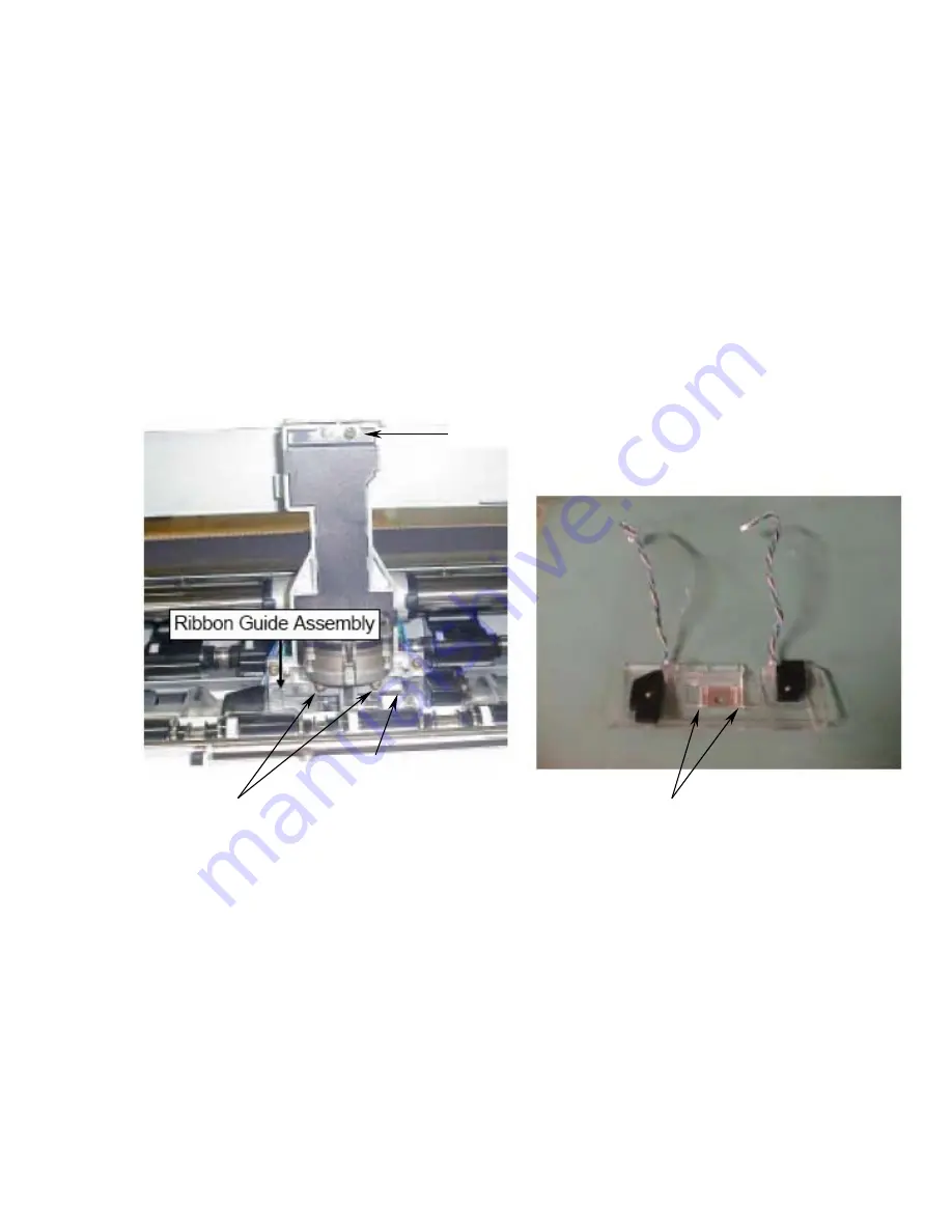
Step 5. Remove 2-pan head screws (S-6) that secure the ribbon guide assembly onto the carrier.
Step 6. Remove the plastic ribbon guide assembly from the carrier.
INSTALLATION
Step 7. Replace the clear plastic ribbon shield assembly. Insert, but do not tighten screws.
Step 8. Use the large white gear left side of the printer chassis to move the carrier up or down.
Position the Carrier Stop .002” (use feeler gauge) above the platen.
Step 9. Place .004” feeler gauges (qty-2) beneath the clear plastic ribbon shield. Place the
gauges alongside the metal ribbon guide. Refer to above picture for reference.
Step 10. Press down and tighten screws (qty-2) securing shield in place. NOTE: Tightening the
screws can sometimes cause the ribbon plastic guide to move out of alignment.
Alternate tightening the screws a small amount until the guide is secured in place.
Step 11. Verify the plastic ribbon guide and platen gap by using a .004” feeler gauge beneath the
clear plastic ribbon shield. Should the gap be incorrect, repeat steps #7 through #11.
Step 12. Reassemble the print head and carrier cover.
Step 13. Reassemble top cover.
Carrier Stop
Place .002” gauge here
Carrier Cover Screw
Print Head Screws
Place .004” Feeler Gauges here
when assembled on the carrier
Summary of Contents for Accel-7350
Page 1: ...1 Accel 7350 Dot Matrix Printer Service Manual Document 130034 ...
Page 24: ...23 Wiring Diagram ...
Page 25: ...24 Control Diagram ...
Page 36: ...35 Extra Dot Printing Improper character ...
Page 37: ...36 Incorrect Printing Irregular print data ...
Page 38: ...37 No LCD Display Half of the LCD lights up ...
Page 39: ...38 No LCD Display Completely blank ...
Page 40: ...39 Control Keys Not Functioning ...
Page 41: ...40 No Buzzer Abnormal Ribbon Feeding Causing abnormal carriage movement ...
Page 42: ...41 No Line Feed or Inconsistent Line Feeding ...
Page 43: ...42 Carriage Error ...
Page 44: ...43 ...
Page 46: ...45 Cover Open Error Will Not Cancel With Cover Closed ...
Page 47: ...46 No Fanfold Paper Reverse Line Feed ...
Page 48: ...47 Printing Does Not Stop After Paper Is Ejected ...
Page 49: ...48 Not Powering Up ...
Page 94: ...93 Indicator Circuit ...
Page 95: ...94 I F Circuit ...
Page 96: ...95 Slide SW Circuit ...
Page 97: ...96 Power Circuit ...
Page 98: ...97 Exploded View 1 6 Following pages require Legal size paper for printing ...
Page 99: ...98 Exploded View 2 6 ...
Page 100: ...99 Exploded View 3 6 ...
Page 101: ...100 Exploded View 4 6 ...
Page 102: ...101 Exploded View 5 6 ...
Page 103: ...102 Exploded View 6 6 ...
Page 119: ...126 ...


