PAGE 5
LS4600 | 6 CHANNEL SPEAKER LINE SURVEILLANCE
Connecting The Unit
24V DC OVERRIDING
CONTROL (EP1200A ETC)
+24V
RS 485
OUTPUT
(OPTIONAL)
VOLUME CONTROLLERS WITH
OVERRIDING RELAY
+24V
-VE
TO SPEAKERS
TO SPEAKERS
FROM ZONE SELECTOR
100V LINE OUTPUT
FROM ZONE SELECTOR
100V LINE OUTPUT
24V DC
POWER
repeat
Loop the 24V DC
overriding trigger to the
Zone Trig. O/P port
Max rating per zone
trigger is 3A. Use
external relay if
required
+VE
-VE
-VE
+VE repeat
add
diode
TO MIMIC PANEL /
EXTERNAL FAULT
INDICATOR ETC
( A DRY CONTACT OUT)
It is recommended that separate zone shall have separate overriding circuit. Otherwise, loop all outputs.
Disadvantage of looping all outputs :
If a particular zone is active (zone on) but the volume controller at a certain area is shut off (eg. zone 1), activation of monitor-
ing from LS4600 of zone 2 shall override the volume controllers at zone 1, thus a burst of audio shall be heard ( such as
BGM being currently played).
Programming And Setup
MAIN MENU
1.0 SETUP
o<>
2.0 MANUAL TEST
o<>
3.0 MEM. RECALL
o<>
4.0 AUTO TEST
o<>
5.0 BUZZER
o<>
6.0 LCD LIGHT
o<>
7.0 MEMORY
o<>
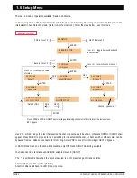
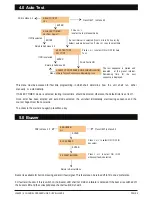
The last part of the unit installation shall be programming as well as entering required values. Program the unit by following
the menus shown in the LCD display panel. Each of the menu and sub menus shall be explained in the following sections.
In general, there are 7 main menus as shown below :
Initializing...
LS4600 VER: X.XX
AMPERES ELEC. S/B
LINE SUPERVISORY
>>
POWER UP
TO ENTER SETUP
1.0 SETUP
o<>
NOTE :
>>
< denotes PRE
> denotes NEXT and
[] as ENTER
Upon powering for the first time, the unit shall display introduction wordings in
running mode. The green and red LEDs shall lit in sequence indicating
sequence of initialisation.
Minumum setup required for the system to run shall be Menu 1.0 and 4.0. If other menus are not set, they shall run according
to default parameters.
To begin programming, press, hold and release MENU button, and
the SETUP menu shall be displayed.

