background image

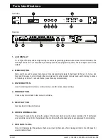
Parts Identifications

PAGE 2

LS4600 | 6 CHANNEL SPEAKER LINE SURVEILLANCE

1

6

8

7

2

3

4

5

9

10

11

12

13

Front view

Rear view

1.   LCD DISPLAY

2.   MENU BUTTON

3.   ENTER BUTTON

Previous key to scroll back to last menu or sub menu.

4.   PREV BUTTON

Next key to scroll forward of menus.

5.   NEXT BUTTON

6.   GREEN NORMAL LEDs

7.   RED FAULT LEDs

2 x 16 digit LCD display with back light setting is used as programming guide as well as measurement indications. The 

back light can be set to off if required by accessing menu 6 (see programming chart). The back light is set to ON in 

default.

Menu switch is used to access main menus. Once pressed momentarily, it shall revert to Menu 1.0 - Setup. Use 

Next and Prev keys to scroll through other main menus. Once the relevant menu is found, use Enter key to access 

its following sub menu. To exit sub menus, press Menu key momentararily. 

Used to enter required main menu or its sub menus, confirm values, data or settings.

The arrays of green LEDs provides the status of the channel which show the normal condition if lit. If both green 

and red LEDs do not lit for the particular channel, it means that the channel has been bypassed from monitoring. 

Once lit, it indicates that the particular channel is at fault ; either open, short or leakage. Refer to the LCD panel for 

exact condition of fault.

Summary of Contents for LS 4600

Page 1: ...ct tapping of line to speakers as well as easier setup without having to trim impedance against a preset reference LS4600 is built and run by a micro controller thus providing a digital platform in se...

Page 2: ...N in default Menu switch is used to access main menus Once pressed momentarily it shall revert to Menu 1 0 Setup Use Next and Prev keys to scroll through other main menus Once the relevant menu is fou...

Page 3: ...ollers set in various position shall have different impedances and such circumstances shall provide false alarm or alert Recommended practice is that every zone shall have its own 24V overriding circu...

Page 4: ...resistors as well as speaker capacitor couplings LS4600 have been improve all accuracy It is recommended that periodical manual checking or setup to be made as connections may deteriorate over time an...

Page 5: ...hus a burst of audio shall be heard such as BGM being currently played Programming And Setup MAIN MENU 1 0 SETUP o 2 0 MANUAL TEST o 3 0 MEM RECALL o 4 0 AUTO TEST o 5 0 BUZZER o 6 0 LCD LIGHT o 7 0 M...

Page 6: ...ccept for monitoring or NEXT to bypass In BASIC Mode Hi and Lo function will be disabled only OPEN and SHORT monitoring available To enable Hi and Lo function use ADVANCE setup in menu 1 0 SETUP The s...

Page 7: ...for high limit and low limits are from 00 ohm to 500 ohm with incremental of 20 Ohms We recommend 50 higher or lower values to avoid unnecessary false triggering Once the required value is selected p...

Page 8: ...re To obtain the actual value use a dedicated Impedance Measurement meter This menu enable the user to view the values of impedance of selected channels which had been accepted earlier during setup Me...

Page 9: ...nu key Return to Submenu 4 0 If Off is selected If a test interval is selected from 1 min to 24 hours By default auto mode is set to off Use or key to select time ENTER If NO is selected Return to Sub...

Page 10: ...y 7 0 MEMORY o 7 0 MEMORY O RESET ENTER Press NEXT to Menu 1 0 PRE to Menu 6 0 7 1 MEMORY SAVE O Y N 7 0 MEMORY O SAVE If earlier settings are to be wiped off use this memory reset and the system shal...

Page 11: ...ut for volume controller overriding during testing mode Operating voltage 24V DC via PS9400 PSU Power consumption 3 5W Capacity 6 channel and expandable Processor PIC micro controller with 12 bit ADC...

Page 12: ...f the purchaser or the dealer for the period out of use of the unit moreover the warranty does not cover any damages which may be caused to people and things when using the product This warranty certi...

Reviews: