background image


Rev: 09.2017 


 EBS Pre-Engineered Skid IOM 


24 


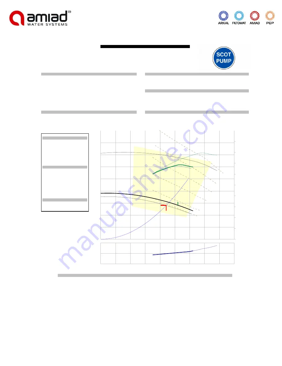
Pump Data Sheet  -  Scot Division of Ardox Corp.

Company: Amiad Water Systems
Name: EBS_10K_883
Date:  2/5/2016

 Pump:

Size:   059-7.0-6.0x5.0
Type:  Endsuct-Encl

Speed:  3500 rpm

Synch speed:  3600 rpm

Dia:  5.625 in

Curve:  40.000.502

Impeller:

Specific Speeds:

Ns:  ---

Nss:  ---

Dimensions:

Suction:  6 in

Discharge:  5 in

 Pump Limits:

Temperature:  300 °F

Power:  ---

Pressure:  175 psi g

Eye area:  ---

Sphere size:  ---

 Search Criteria:

Flow:  883 US gpm

Head:  70 ft

Near miss:  5 % of Head

 Fluid:

Water

Temperature: 60 °F

SG:  1

Vapor pressure:  0.2563 psi a

Viscosity:  1.105 cP

Atm pressure:  14.7 psi a

NPSHa:  ---

 Motor:

Size:  30 hp

Speed:  3600

Frame:  286TS

Standard:  NEMA

Enclosure:  TEFC

Sizing criteria:  Design Point

 Selected from catalog:  Scot.60  Vers: 10.1

---- Data Point ----

Flow:

883 US gpm

Head:

77.4 ft

Eff:

65%

Power:

26.3 hp

NPSHr:

19.4 ft

---- Design Curve ----

Shutoff head:

95.2 ft

Shutoff dP:

41.2 psi

Min flow:

---

BEP:

68% @ 1042 US gpm

NOL power:

27.9 hp @ 1236 US gpm

-- Max Curve --

Max power:

72.6 hp @ 1568 US gpm

US gpm

NP

SH

ft

1600

1400

1200

1000

800

600

400

0

200

20

40

Head 

ft

Efficien

cy

0

10

20

30

40

50

60

70

80

90

1600

0

1400

25

1200

50

1000

75

100

800

125

600

150

400

175

200

200

68.3

5.625 in

7 in

5.5 in

25 hp

30 hp

40 hp

50 hp

60 hp

75 hp

 Performance Evaluation:

Flow

Speed

Head

Efficiency

Power

NPSHr

US gpm

rpm

ft

%

hp

ft

1060

3500

69.3

68

27.2

21.8

883

3500

77.4

65

26.3

19.4

706

3500

84.8

60

25.1

17.1

530

3500

87.5

56

24

14.8

353

3500

---

---

---

---

Summary of Contents for EBS 1006

Page 1: ...m Amiad If you received this file in error please notify Amiad immediately The confidential nature of and or privilege in the file enclosed is not waived or lost as a result of a mistake or error in this file Amiad accepts no liability whatsoever whether it was caused by 1 Accessing or other related actions to this file 2 Any links procedures or materials provided attached to this file Amiad assum...

Page 2: ...fety instructions 4 Description and filter operation 5 Installation 6 Commissioning Start up and First Operation 7 Maintenance 8 Troubleshooting 10 Disassembling and reassembling 11 Parts schedule and drawings 14 Parts schedule drawing skid and parts 22 Pump curves 23 Level I Controller 26 Appendix 1 Pump IOM 36 ...

Page 3: ... 10000 1500 25 50 230 460 28 4 4 FLG 8 3 FLG 220 111 1456 1606 2072 EBS 883 883 10000 1500 30 50 230 460 33 7 6 FLG 8 3 FLG 220 111 1519 1669 2135 EBS 1006 1006 10000 1500 30 50 230 460 33 7 6 FLG 8 3 FLG 220 111 1519 1669 2135 Dimensions inches MODEL A B C D E F G H I J K EBS 769 14 875 1 812 3 5 15 875 8 875 11 937 71 312 48 5 114 687 65 5 39 875 EBS 883 15 625 3 125 3 5 15 875 7 687 11 937 72 1...

Page 4: ...ll the filter according to the instructions in this manual 2 Leave enough clearance for easy access to all components and safe maintenance operations 3 Electric wiring should be performed by an authorized electrician only using standardized and approved components 4 Install a main power cut off switch close to the control panel 5 If the control panel cannot be seen from the filter s a power cut of...

Page 5: ... During the self cleaning process which takes approximately 35 seconds filtered water continues to flow out of the filter System Operation modes The filtration system may be found in one of the following modes 1 Filtering mode This is the normal operating status The flush mode is idle and the power light on the control board is lit 2 Self cleaning mode The motor and exhaust valve are activated acc...

Page 6: ...y other local safety instructions 2 Select a convenient location for the installation of the filter where operation and maintenance will be optimal It is recommended that a standard and safe lifting auxiliary is available for maintenance 3 Install the filter vertically Please note that a minimum clearance of 300 mm 12 In Not including a crane is required in order to allow disassembly of the unit 4...

Page 7: ...n and make sure that it is installed in accordance with the official installation drawings 3 Verify by authorized electrician only that the electric wiring is correct and complies with the enclosed drawings Make sure that the electrical start up operation is done by an authorized electrician only 4 Switch the control 24V circuit breakers Leave the motor OL protector OFF 5 Toggle all limit switches...

Page 8: ...add grease to the filter s suction scanner shaft 5 Take care of any leakage from the scanner shaft If necessary replace the Sealing Flange Internal O Ring 5 on page 23 as described at the following list 6 Reconnect the filter carefully and safely to its water air and power supply 7 Perform a General Inspection of the Filter Operation as described above Changing the sealing flange internal O ring 1...

Page 9: ... operation b Any leakage from the filter housing or accessories c Abnormal or unusual noises d Loosen bolts e Non smooth turning of the suction scanner f Unusual load on the filter electrical motor g Any sign of corrosion on the filter housing or accessories h Unusual vibrations i Non smooth operation of the filter valves air release valves and check valves 2 Close the inlet and the outlet valves ...

Page 10: ... switch if found faulty The motor protector was activated The fault indication lamp is blinking in red This fault means that the motor was operated under too high load Note All the following checks and actions should be done by a qualified electrician only A Check the motor power consumption when not loaded B Check the limit switches for correct operation and verify that each one of them stop the ...

Page 11: ...ner shaft 2 on page 24 8 Unscrew bolts 10 on page 23 and remove the limit switches sling 9 on page 23 without disconnecting and changing the limit switches position 9 Unscrew bolts 20 connecting the shaft housing 17 to the filter lid 12 10 Pull up the shaft housing Put it near the filter make sure not to damage the limit switches electric wires If necessary disconnect the wires from the connecting...

Page 12: ...t a quarter from top Make sure that the extractor cushions do not touch the stitch found along the screen interior 4 Pull the extractor up so that it is firmly set against the inside wall of the Screen Figure 2 Figure 2 5 Attach a lifting device to the ring on the Extractor and extract Never lift the screen above people or equipment ...

Page 13: ...in opposite positions 6 Screw the rest of the housing bolts 13 Tightening opposite positioned bolts will achieve proper sealing 7 Locate the O ring 16 in its groove under the shaft housing 17 Place the bolts 20 but do not yet tighten them firmly 8 Turn the drive shaft 3 on page 23 clockwise until it reaches the suction scanner shaft Insert the connecting pin 18 into the hole in the drive shaft thr...

Page 14: ... P 2 471 NBR 1 NBR 10 710103 002611 Upper Bearing EBS 1 Delrin 11 770102 000077 O Ring Seal P2 041 External Upper Bearing NBR 1 NBR 12 710105 XXXXXX Lid EBS 10000 Filter Epoxy PKPK 3002 1 ST 37 2 13 760101 000375 Hex Bolt Partial Thread M22X100 Zinc Plated C ST 16 Zinc Plated 14 760103 000079 Flat Washer M22 DIN125 Zinc Plated C ST 32 Zinc Plated 15 760102 000069 Hex Nut M22 Zinc Plated C ST DIN93...

Page 15: ...ter Valve 1 4 W Drain 1 Brass 33 720501 000214 T Connector 1 4 FxFxM Brass 2 Brass 34 720501 000202 L Connector 5 16 X1 4 4 Brass 35 730104 000202 Valve 3 Way 1 4 1 Brass 36 720501 000204 L Connector 5 16 X1 8 3 Brass 37 720301 000044 Pressure Gauge 1 4 DI w PSI Bottom Inlet 1 Brass 38 720501 000206 Connector 5 16 x1 4 2 Brass 39 730104 000220 Ball Valve 3 4 M F BRASS 2 Brass 40 710103 002659 Brac...

Page 16: ...I Iso16 Pr 1 Cast Iron 54 760101 000329 Hex Bolt Partial Thread M16X65 Zinc Plated C ST 8 Zinc Plated 55 780101 000789 L Connector 3 4 F M Galvanized 1 ST 37 2 Galvanized 56 010000 000042 3 4 Black Filter AC W O Valve Nylon Screen 200 Mic 1 Various 57 710103 002569 Raccord Nipple 1 4 for 3 4 Filter 1 ABS medium impact 58 770102 000082 O Ring Seal P2 112 NBR 1 NBR 59 710103 002570 Raccord Nut 3 4 f...

Page 17: ...Rev 09 2017 EBS Pre Engineered Skid IOM 17 PARTS DRAWING Section 1 Page 1 1 9 2 3 4 5 6 7 8 19 18 6 15 14 10 11 5 14 13 22 21 12 16 24 21 20 17 23 29 28 27 25 30 27 26 31 ...

Page 18: ...017 EBS Pre Engineered Skid IOM 18 PARTS DRAWING Section 1 Page 2 39 32 33 34 34 33 38 62 62 62 50 46 44 47 45 48 49 37 36 62 36 35 62 21 54 52 34 36 38 61 60 53 62 21 22 41 42 43 51 51 34 57 58 59 56 39 55 40 ...

Page 19: ...read M6X20 S ST316 DIN933 2 S ST 316 11 760101 000683 Phillips Pan Machine Screw M4X20 S ST316 4 S ST 316 12 760103 000122 Flat Washer M4 DIN125 S ST316 4 S ST 316 13 760102 000085 Hex Nut M6 S ST316 DIN934 2 S ST 316 14 720302 000004 Flat Washer M10 DIN125 S ST316 2 S ST 316 15 760101 000527 Socket Set Screw M10X50 S ST316 DIN916 2 S ST 316 16 760101 000605 Hex Bolt Full Thread M6X35 S ST316 DIN9...

Page 20: ...Rev 09 2017 EBS Pre Engineered Skid IOM 20 PARTS DRAWING Section 2 3 8 7 1 8 21 2 17 5 4 22 15 20 6 23 11 14 12 18 9 10 8 8 19 13 16 A ...

Page 21: ...nner EBS 10K 15K 1 S ST 316L 6 710103 002827 Plug POM for Internal Filter 1 Delrin 7 760105 000042 PIN 3 X 20 S ST316 1 S ST 316 8 710103 002964 Housing for SLN EBS 6 S ST 316L 9 710103 002962 Cap for Nozzle EBS Spring Loaded 6 NYLON 12 10 770101 000046 O Ring Seal 18x2 NBR 6 NBR 11 710103 002963 Tightening Nut for Nozzle EBS Spring Loaded 6 Delrin 12 770104 000100 Spring Loaded Nozzle Seal EBS RE...

Page 22: ... HP SCOT 57 WEG 256JM SF BN EBS 10K 769 GPM 720401 000624 30 HP SCOT 59 WEG 286JM SF BN EBS 10K 883 GPM 720401 000625 30 HP SCOT 59 WEG 286JM SF BN EBS 10K 1006 GPM 720401 000625 Seal kits SEAL KIT FOR SCOT PUMP 57 EBS 10K 769 GPM 720401 000533 SEAL KIT FOR SCOT PUMP 59 EBS 10K 883 GPM 118 000 530 SEAL KIT FOR SCOT PUMP 59 EBS 10K 1006 GPM 118 000 530 ...

Page 23: ...25 hp Speed 3600 Frame 284TS Standard NEMA Enclosure TEFC Sizing criteria Design Point Selected from catalog Scot 60 Vers 10 1 Data Point Flow 769 US gpm Head 76 2 ft Eff 66 Power 22 1 hp NPSHr 15 8 ft Design Curve Shutoff head 129 ft Shutoff dP 55 7 psi Min flow BEP 74 632 US gpm NOL power 22 4 hp 866 US gpm Max Curve Max power 40 hp 1000 US gpm US gpm NPSHr ft 1000 900 800 700 600 500 400 300 20...

Page 24: ... 30 hp Speed 3600 Frame 286TS Standard NEMA Enclosure TEFC Sizing criteria Design Point Selected from catalog Scot 60 Vers 10 1 Data Point Flow 883 US gpm Head 77 4 ft Eff 65 Power 26 3 hp NPSHr 19 4 ft Design Curve Shutoff head 95 2 ft Shutoff dP 41 2 psi Min flow BEP 68 1042 US gpm NOL power 27 9 hp 1236 US gpm Max Curve Max power 72 6 hp 1568 US gpm US gpm NPSHr ft 1600 1400 1200 1000 800 600 4...

Page 25: ...ze 30 hp Speed 3600 Frame 286TS Standard NEMA Enclosure TEFC Sizing criteria Design Point Selected from catalog Scot 60 Vers 10 1 Data Point Flow 1006 US gpm Head 72 2 ft Eff 68 Power 27 1 hp NPSHr 21 ft Design Curve Shutoff head 95 2 ft Shutoff dP 41 2 psi Min flow BEP 68 1042 US gpm NOL power 27 9 hp 1236 US gpm Max Curve Max power 72 6 hp 1568 US gpm US gpm NPSHr ft 1600 1400 1200 1000 800 600 ...

Page 26: ...ediately The confidential nature of and or privilege in the file enclosed is not waived or lost as a result of a mistake or error in this file Amiad accepts no liability whatsoever whether it was caused by 1 Accessing or other related actions to this file 2 Any links procedures or materials provided attached to this file Amiad assumes that all users understand risks involved within this file and o...

Page 27: ...Product Description 30 3 1 Functional Description 30 3 2 Standard Component Description 30 Disconnect Switch 30 Contactor and Overloads 30 Transformer 31 Adjustable Flush Interval Timer 31 Programmable Logic Controller PLC 31 Power On Light 31 Flush Pushbutton 31 Fault Reset Pushbutton and Light 31 3 3 Transportation 32 3 4 Communication 32 4 Operation 32 4 1 Initial Operation 32 4 2 Deactivation ...

Page 28: ...n expect many years of service from this equipment Amiad wants to be sure that this equipment meets all of your needs We depend upon your feedback to make necessary upgrades and improvements Please contact our office with any comments or questions We look forward to assisting you with this product and any future filter system needs Amiad Water Systems 120 J Talbert Road Mooresville NC 28117 Toll F...

Page 29: ... training shall operate and maintain the Amiad equipment Work on electronic components should only be performed by qualified personnel The term qualified personnel includes persons able to implement the required activities in each case on the basis of their vocational training and experience as well as their knowledge of relevant and applicable standards and regulations on the prevention of accide...

Page 30: ...c technical data 3 1 Functional Description Utilizing a start command as described in the Product Description for the self cleaning cycle the system is designed to be self sufficient There is no need to interfere with the filter as the equipment uses the highest level of technology to control the filter system Typical start command is given by a differential pressure switch however a variety of in...

Page 31: ... initiate one self cleaning cycle every day at a minimum This is a high performance timer with 8A contacts and the ability to set the interval from 0 05 seconds to 60 hours Programmable Logic Controller PLC The Programmable Logic Controller PLC is designed to handle all of the controls It is used to simplify the operation thereby making the overall controller more robust It has a special program d...

Page 32: ...l Operation Always use the appropriate Personal Protective Equipment PPE when working with electrical components With the electrical source isolated connect the appropriate electrical connections to the Amiad Controller Check on the data plate to ensure the appropriate power supply is connected Add necessary short circuit protection as required on schematic Ensure pump is appropriately supplied wi...

Page 33: ...ition Turn all circuit breakers to the off position Apply appropriate lock out tag out measures to ensure that power is not accidentally switched on 5 Electro mechanical Controls Standard settings are set at the factory These settings are specific to the customer s application There is however a wide range of flexibility with this product The image above is the timing chart for the Flush Interval ...

Page 34: ...btener el tiempo de lavado adecuado Réglez le grand cadran sur TR1 pour obtenir le temps de rinçage approprié Small Dial Number Pequeño número de marcación Petit numéro d appel Large Dial number Número de marcación grande Un grand nombre de numérotation Actual Time Tiempo real Temps réel 1h 5 30m 1h 1 0 1h 3h 1 0 3h 10h 8 8h 60h 4 24h Set the dials on TR2 to get the flush interval time Ajuste los ...

Page 35: ... Major Faults and one Major Fault which can occur when a suction pump is used during the self cleaning flush cycle 1 Differential Pressure Fault the self cleaning flush cycle has not been able to clear the differential pressure for a programmed period of time factory set at 240 seconds The differential pressure must be cleared by power flushing the filter system or by manually cleaning the filter ...

Page 36: ...Rev 09 2017 EBS Pre Engineered Skid IOM 36 Appendix 1 Pump IOM ...

Page 37: ...INSTALLATION AND MAINTENANCE INSTRUCTIONS FOR ELECTRIC MOTORS Frames 143 5T 586 7T ...

Page 38: ...d lowering must be done gently without any shocks otherwise the bearings can get damaged DURING TRANSPORTATION MOTORS FITTED WITH ROLLER OR ANGULAR CONTACT BEARINGS ARE PROTECTED AGAINST BEARING DAMAGES WITH A SHAFT LOCKING DEVICE HANDLINGAND TRANSPORTATION RECEIVING CHECK READ CAREFULLY THIS MANUAL BEFORE INSTALLING THE MOTOR MOTORS MUST NOT BE LIFTED BY THE SHAFT BUT BY THE EYE BOLTS WHICH ARE P...

Page 39: ...otor is fitted with space heaters these should be switched on Insulation Resistance Check Insulation Resistance Check Insulation Resistance Check Insulation Resistance Check Insulation Resistance Check Measure the insulation resistance before operating the motor and or when there is any sign of humidity in the winding The resistance measured at 25 C 77o F must be Ri 20 x U 1000 2P Mohm measured wi...

Page 40: ...itions Electric motors in general are designed for operation at an altitude of 1000m above sea level for an ambient temperature between 25 C 77 F and 40 C 104 F Any variation is stated on the nameplate Motors must be protected against accidental starts When performing any maintenance service disconnect the motor from the power supply Make sure all accessories have been switched off and disconnecte...

Page 41: ...PLICATION WITH THE DATA GIVEN ON THE NAMEPLATE 3 Foundation Motors provided with feet must be installed on though foundations to avoid excessive vibrations The purchaser is fully responsible for the foundation Metal parts must be painted to avoid corrosion The foundation must be uniform and sufficiently tough to support any short circuit strengths It must be designed in such a way to stop any vibr...

Page 42: ...ls to protect the bearings Suitable assembly of half coupling check that clearance Y is less than 0 05mm and that the difference X1 to X2 is less than 0 05m as well Transmission elements such as pulleys couplings etc must be dynamically balanced with half key before installation Use always appropriate tools for installation and removal 6 Alignment ALIGN THE SHAFT ENDS AND USE FLEXIBLE COUPLING WHE...

Page 43: ...motors can retain a charge which appears across the motor terminals even when the motor has reached standstill W W W W WARNING ARNING ARNING ARNING ARNING Excessive tension on the pulleys will damage the bearings and lead to a probable shaft rupture Voltage and connection are indicated on the nameplate The acceptable voltage variation is 10 the acceptable frequency variation is 5 and the total acc...

Page 44: ...nd application analysis The rotation direction is clockwise if the motor is viewed from DE side and if the phases are connected according to the sequence L1 L2 L3 To change the rotation direction interchange two of the connecting leads Make sure to use the correct cable dimension based on the rated current stamped on the motor nameplate BEFORE ENERGIZING THE TERMINALS CHECK IF THE EARTHING IS MADE...

Page 45: ...comes from a neighbour machine Periodical vibration checks must be done c Run the motor under rated load for a short period of time and compare if the running current is equal to that stamped on the nameplate 1 General Inspection 9 Check the motor periodically 9 Keep the motor clean and assure free air flow 9 Check the seals or V Ring and replace them if required 9 Check the connections as well as...

Page 46: ...aring housing When this is not possible due to turning parts by the grease device pulleys bushing etc that offer some risk to the physical integrity of the operator proceed as follows 9 Clean the area near to the grease nipple 9 Put approximately half of the total grease and run the motor for 1 minute at full speed Then turn off the motor and pump the rest of the grease 9 The injection of all the ...

Page 47: ... 20000 586 7TS 27 3600 4500 9700 11600 14200 16400 17300 19700 20000 20000 20000 Relubrication intervals in hours cylindrical roller bearings 324 5T 21 9800 11900 20000 20000 20000 20000 20000 20000 20000 20000 20000 364 5T 27 9700 11600 14200 16400 17300 19700 20000 20000 20000 404 5T 34 6000 7600 9500 11600 13800 15500 15500 17800 20000 444 5T 45 4700 6000 7600 9800 12200 13700 13700 15700 20000...

Page 48: ...5T to 586 7T frame motors For every 15o C 59o F above these limits relubrication interval must be reduced by half Shielded bearing ZZ are lubricated for berings life as long as they operate under normal ambient conditions and temperature of 70 C 158o F WE RECOMMEND TO USE BALL BEARINGS FOR MOTORS DIRECTLY COUPLED TO THE LOAD WARNING EXCESS OF GREASE CAN CAUSE BEARING OVERHEATING RESULTING IN COMPL...

Page 49: ...i oxidant additive Notes Notes Notes Notes Notes 9 Although Polyrex EM is compatible with the types of grease given above we do no recommend to mix it with any other greases 9 If you intend to use a type of grease different than those recommended above first contact WEG 9 On applications with high or low temperatures speed variation etc the type of grease and relubrication interval are given on an...

Page 50: ...E THE ENVIRONMENT CHARACTERISTICS Motors for hazardous locations are manufactured according to specific standards for such environments and they are certified by worldwide certifying entities 1 Installation The complete installation must follow procedures given by the local legislation in effect and to avoid damages New bearings shall only be taken out from their cases when assembling them Before ...

Page 51: ...NG AT THE RATED CURRENT ANY ELECTRICAL OR MECHANICAL MODIFICATION MADE ON HAZARDOUS LOCATION MOTORS WILL VOID THE CERTIFICATION DO NOT REUSE DAMAGED OR WORN PARTS REPLACE THEM BY NEW ONES SUPPLIED BY THE FACTORY When performing maintenance installation or relubrication follow these instructions 9 Check if all components are free of edges knocks or dirt 9 Make sure all parts are in perfect conditio...

Page 52: ...llows 9 Lower efficiency 9 Higher vibration 9 Higher noise level 9 Higher rated current 9 Higher temperature rise 9 Reduced motor insulation 9 Reduced bearing life 1 Standard Motors 9 Voltages lower than 440V do not require filter 9 Voltages equal or higher than 440V or lower than 575V require filter for motor power supply cables longer than 20 meters 9 Voltages equal or higher than 575V require f...

Page 53: ...e and corresponding repair Immediate notice by the purchaser about failures occured and that these are accepted by WEG as manufacturing defects This warranty does not include disassembly services at the urchaser facilities transportation costs with product tickets accomodation and meals for technical personnel when requested by the customer The warranty service will be only carried out at WEG Auth...

Reviews: