Page 22
Setting Volume Zones
The Rock-Star Lx Digital Downloading Jukeboxes
have the capability of controlling up to four
independent volume zones when using Rowe’s IR
Remote, Rock-Ola’s Multi-Zone Volume Control, or
Rowe’s Digital Volume Control Unit (VCU). An
optional power amplifier may be required for some
situations.
Volume Control (Zone) Linking
There may be times when you do not want a location
to have separate control of the internal and external
amplifiers. Or perhaps you want two or more areas to
have separate volume control. SyberSonic’s
advanced electronic system allows “linking” of its
volume controls.
When linked, pressing either the Internal or External
(1 and 2 on remote) buttons will cause the linked
channels volume to change.
Indicator LEDs
The Digital SyberSonic Pre-Amplifier has LEDs to
give a visual indication of its operating condition and
status. The LEDs and their functions are as follows:
Power -
When lit it indicates the amplifier has power.
Status -
Indicates when the paging system
(microphone) is active.
Steady On –
Normal operation. Paging system is
available.
Flashing –
Paging system is in use.
COM
–
Indicates when the pre-amplifier receives
instructions from the jukebox’s Core Computer.
Always Off –
Indicates a communication fault
between the pre-amplifier and Core Computer.
Single One Second Flash on Power Up –
Pre-
Amplifier Processor is running.
Steady Heartbeat –
Normal operation
communicating with the Core. Setup instructions
received and installed.
Steady On –
Communication fault. Pre-Amplifier
initially received computer commands, but then
lost communication.
Flickering or Intermittent Flashing –
Pre-
Amplifier is receiving instructions from Jukebox
Core Unit.
Mute –
When lit it indicates the control amp outputs
are muted.
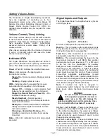
Signal Inputs and Outputs
The Digital SyberSonic Pre-Amplifier has five (5) sets
of RCA type jacks.
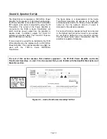
Figure 4-C – RCA Jacks
Each set of RCA jacks has separate functions:
Main In
–
This connection is the audio signal that is
being fed directly from the Sound Card in the Core
Unit Audio Output into the pre-amplifier.
Fixed Out
–
This connection is an unconditioned
analog audio output from the Core unit.
BGM In
–
This connection allows the input of a line
level signal (maximum 1 volt RMS) from another
audio source (such as a tape player, TV, or FM tuner)
to be fed into the pre-amplifier for auxiliary
background music amplification. The BGM volume
level may be set separately, or linked to change
along with the normal play volume. The background
music inputs have level trim controls. These are small
screw-driver adjustable potentiometers located
between the two RCA jacks. Carefully adjust them to
set the level of the background music as desired. The
AVC will act on this signal to try and maintain it even
if the location changes the level externally.
Note:
If enabled, this input is designed to
automatically switch between the AUX BGM and
Main inputs, where the Main input always takes
priority.
WARNING
Do not connect the AUX BGM Inputs
to the speaker outputs of a receiver or
power amp, as this will damage the
jukebox amplifier and void its warranty. Use a
line converter with an actuator if necessary.
Int. Out
-
Left & Right –
These connections are a
variable-level output signal directly from the pre-amp.
In the default configuration, the signal level follows
the internal volume control. If the optional Multi-Zone
Volume Control is used, channels 1 and 2 control
these signal levels respectively.
Ext. Out
-
Left & Right –
These connections are a
variable-level output signal directly from the pre-amp.
In the default configuration, the signal level follows
the external volume control. If the optional Multi-Zone
Volume Control is used, channels 3 and 4 control
these signal levels respectively.
!
Summary of Contents for Rock-Star Lx
Page 1: ...22022611 Rev C Installation Owner s Manual ...
Page 2: ......
Page 25: ...Page 23 Section D Service Maintenance Routine Maintenance Schedule ...
Page 30: ...Page 28 Front Door INSIDE VIEW ...
Page 34: ...Page 32 Inside and Outside Cabinet INSIDE CABINET LOCK PARTS 26 25 23 22 24 ...
Page 41: ...Page 39 Harnesses 10 34022338 11 34022342 12 34033235 13 34037940 14 34100303 15 34099901 ...


