16
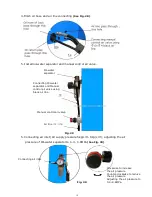
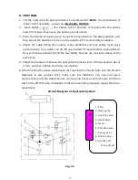
L. Install hydraulic system
(See Fig. 25).
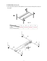
Note: Oil hoses connected to oil cylinder must be passed above the cable, cylinder
inlet port must swing upward to avoid the oil hose and oil return pipe scratched
by cable.
M. Install air-line system
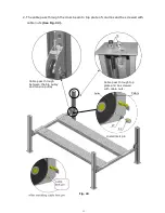
1. Cut the
¢
6
×¢
4 black air lines of cross beams between the two retainers, and then
connect with T-Fitting
(See Fig. 26)
.
d
c
b
a
Retainer
Protective Ring
Fig. 25
cylinder inlet
port swing
upward
Summary of Contents for PRO-14
Page 1: ...FOUR POST LIFT PRO 14...
Page 2: ......
Page 4: ......
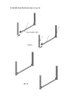
Page 11: ...7 D Install cross beams See Fig 11 Fig 12 Fig 11 Hole towards inside 1 3 2 3 Fig 12...
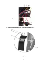
Page 25: ...21 O Install spring and safety cover of cross beam See Fig 34 Fig 34 3 3 3 8 40 3 2 Fig 33...
Page 27: ...23 IV EXPLODED VIEW Model PRO 14 Fig 36...
Page 28: ...24 3 73 74 CROSS BEAM CYLINDERS Fig 37 Fig 38...
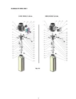
Page 29: ...25 MANUAL POWER UNIT Fig 39 220V 50HZ 1 phase 380V 50HZ 3 phase...
Page 39: ......


