


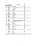
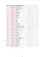


20
Three phase motor
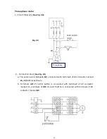
1.
Circuit Diagram
(See Fig. 32)
.
2.
Connection step
(See Fig. 33)
a. The source wires (
L1, L2, L3
) connected with terminals of AC contactor marked
L1, L2, L3
respectively.
b. Terminals
4#
of control button is connected with terminals of AC contactor
marked L1, terminals of
3#
of contorl button is connected with terminals of AC
contactor marked
A1
.
Fig. 32
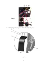
Push button
Three phase
Summary of Contents for PRO-14
Page 1: ...FOUR POST LIFT PRO 14...
Page 2: ......
Page 4: ......
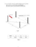
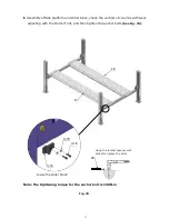
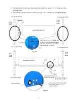
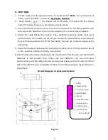
Page 11: ...7 D Install cross beams See Fig 11 Fig 12 Fig 11 Hole towards inside 1 3 2 3 Fig 12...
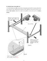
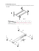
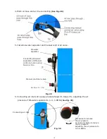
Page 25: ...21 O Install spring and safety cover of cross beam See Fig 34 Fig 34 3 3 3 8 40 3 2 Fig 33...
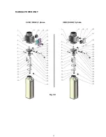
Page 27: ...23 IV EXPLODED VIEW Model PRO 14 Fig 36...
Page 28: ...24 3 73 74 CROSS BEAM CYLINDERS Fig 37 Fig 38...
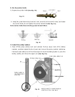
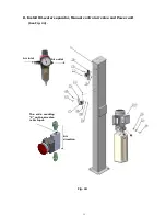
Page 29: ...25 MANUAL POWER UNIT Fig 39 220V 50HZ 1 phase 380V 50HZ 3 phase...
Page 39: ......