26
Illustration of hydraulic valve for power unit
a. manual power unit, 220V/50HZ, Single phase (See Fig. 40)
b. Manual power unit, 380V/50HZ, Three phase (See Fig. 41)
Fig. 40
Fig. 41
Relief valve
Check valve
Release valve
Oil Outlet
Oil return port
Handle of Release
valve
Throttle valve
Release valve
Handle of Release
valve
Check valve
Oil return port
Oil Outlet
Relief valve
Throttle valve
Protective
ring
Protective
ring
Summary of Contents for PRO-14
Page 1: ...FOUR POST LIFT PRO 14...
Page 2: ......
Page 4: ......
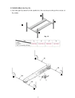
Page 11: ...7 D Install cross beams See Fig 11 Fig 12 Fig 11 Hole towards inside 1 3 2 3 Fig 12...
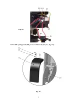
Page 25: ...21 O Install spring and safety cover of cross beam See Fig 34 Fig 34 3 3 3 8 40 3 2 Fig 33...
Page 27: ...23 IV EXPLODED VIEW Model PRO 14 Fig 36...
Page 28: ...24 3 73 74 CROSS BEAM CYLINDERS Fig 37 Fig 38...
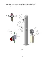
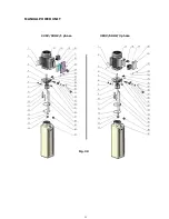
Page 29: ...25 MANUAL POWER UNIT Fig 39 220V 50HZ 1 phase 380V 50HZ 3 phase...
Page 39: ......

