


Released 06/2010
E-mail: [email protected]; [email protected]; website: www.amfreece.com
Phone: +420 582 309 286; Fax: +420 582 360 606
DECO 2000
1-27
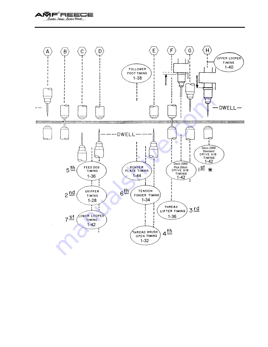
* — SEQUENCE IN
E - STANDARD MACHINE ADJUSTMENT
Released 06/2010
E-mail: [email protected]; [email protected]; website: www.amfreece.com
Phone: +420 582 309 286; Fax: +420 582 360 606
DECO 2000
1-27
* — SEQUENCE IN
E - STANDARD MACHINE ADJUSTMENT